
Photovoltaic module with adjustable heat sink and method of fabrication

a photovoltaic module and heat sink technology, applied in the field of photovoltaic modules, can solve the problems of reducing the performance of photovoltaic reducing the power output of both types of modules at elevated temperatures, and reducing the power output of both types of modules

Inactive Publication Date: 2006-06-29
SCHRIPSEMA JASON E +1
View PDF99 Cites 61 Cited by
  • Summary
  • Abstract
  • Description
  • Claims
  • Application Information

AI Technical Summary

Benefits of technology

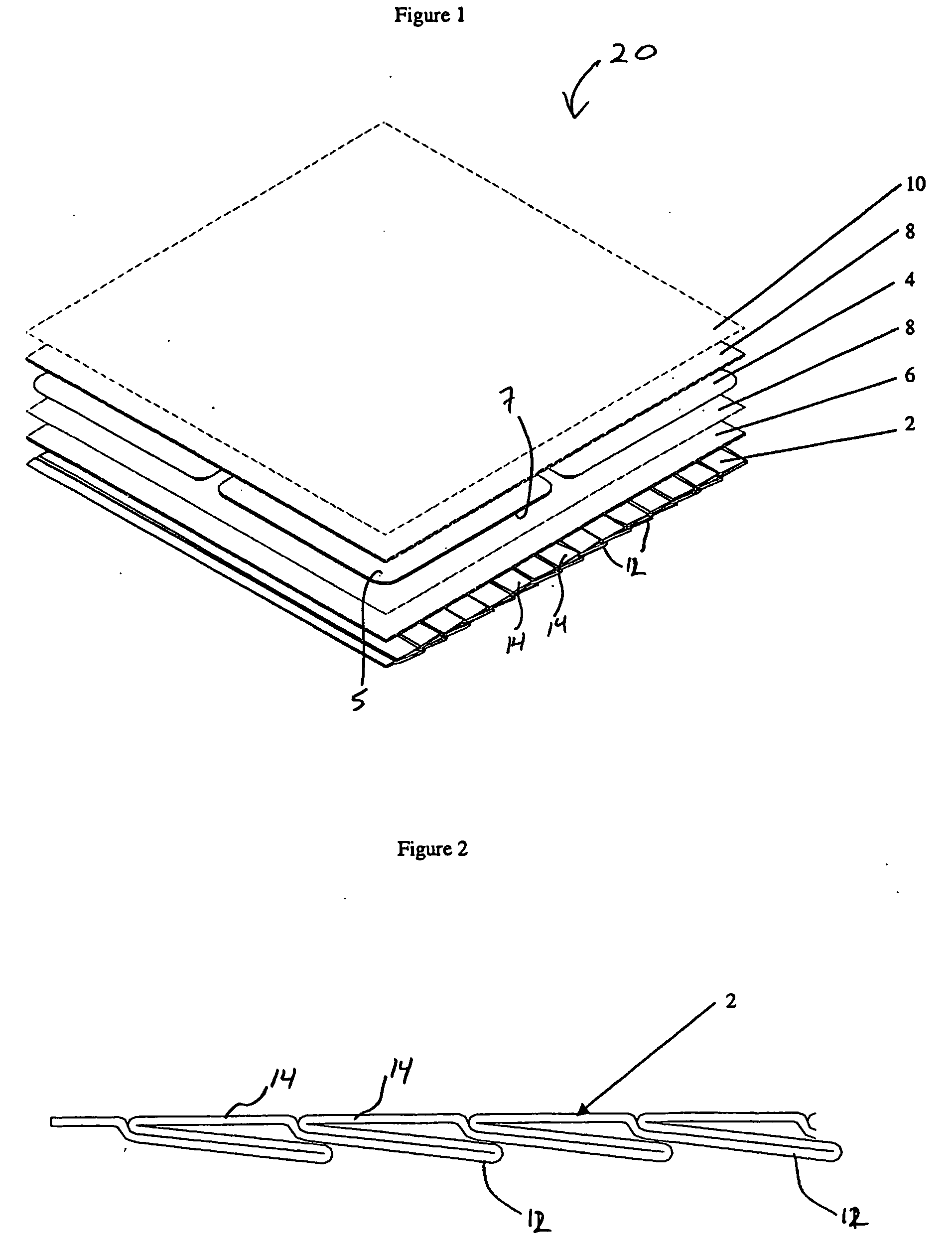
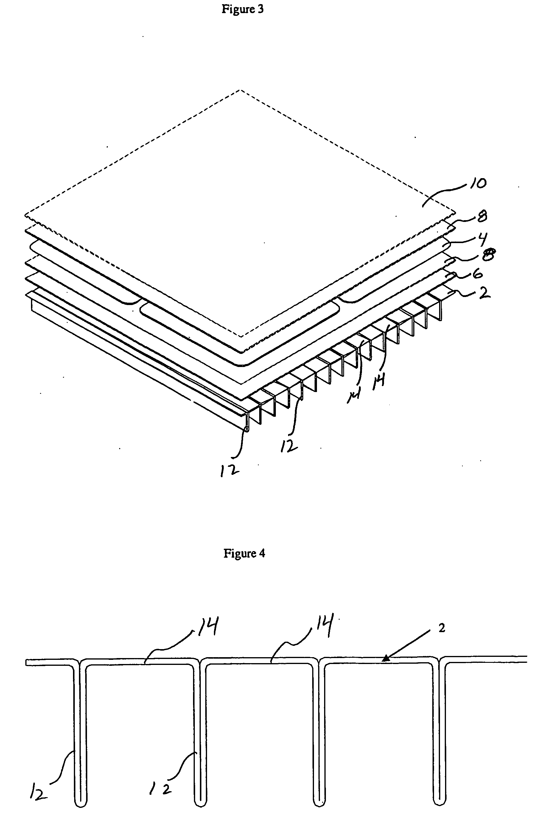
[0005] The present invention provides a photovoltaic module comprising a photovoltaic material and a heat sink in thermal communication with the photovoltaic material proximate a mounting surface of the heat sink. The photovoltaic material may be provided as a photovoltaic cell. The heat sink comprises a plurality of fins that are movable between a first position substantially parallel to the mounting surface of the heat sink and a second position non-parallel to the mounting surface of the heat sink. Orientation of the fins in the first parallel (or flattened) position may be particularly desirable during fabrication of the module, when the heat sink is attached to the photovoltaic material to facilitate, for example, lamination of the heat sink to the photovoltaic material.

Problems solved by technology

One source of inefficiency, and decreased power output, is a decrease in performance of photovoltaic modules at elevated temperatures.
Both types of modules suffer from reduced power output at elevated temperature.

Method used


Image

  • Photovoltaic module with adjustable heat sink and method of fabrication
  • Photovoltaic module with adjustable heat sink and method of fabrication
  • Photovoltaic module with adjustable heat sink and method of fabrication

Examples


Embodiment Construction

[0013] Referring now to the drawings wherein like reference numerals refer to the same or similar elements across the several views, and in particular to FIG. 1, there is shown an exploded view of a photovoltaic module 20 in accordance with the present invention. The photovoltaic module 20 comprises a photovoltaic material, which may conveniently be provided in the form of one or more discrete photovoltaic cells 4 or thin film photovoltaic materials. The photovoltaic cells 4 are generally planar in shape, and may conveniently have a rectangular shape. However, other shapes, including non-planar shapes, may be used in accordance with the present invention.

[0014] The photovoltaic cells 4 may comprise semiconductor materials in which electron-hole pairs are created when exposed to light to provide an electrical current flow when the photovoltaic module 20 is connected to an electrical circuit. The photovoltaic cells 4 may be manufactured from crystalline silicon, amorphous silicon, co...


PUM


Abstract

The present invention provides a photovoltaic module (20) comprising a photovoltaic material and a heat sink in thermal communication with the photovoltaic material proximate a mounting surface of the heat sink. The heat sink comprises a plurality of fins (12) that are movable between a first position parallel to the mounting surface and a second position non-parallel to the mounting surface. Orientation of the fins in the first position may be particularly desirable during fabrication of the module when the heat sink is attached to the photovoltaic material. As such, the present invention provides a method for fabricating a photovoltaic module comprising providing a photovoltaic material and providing the heat sink having movable fins. The fins are oriented in the first position and the heat sink is then attached to the photovoltaic material. After the heat sink is attached, the fins may be unfolded into the second position.

Description

FIELD OF THE INVENTION [0001] The present invention relates generally to a photovoltaic device, and in particular but not exclusively a photovoltaic module having an adjustable heat sink and method for the fabrication of such a module. BACKGROUND OF THE INVENTION [0002] Photovoltaic modules currently enjoy broad commercial use. For example, in terrestrial applications, photovoltaic modules are typically used to power remote electronic equipment such as radio towers, microwave repeater stations, and navigation buoys. Photovoltaic modules are also used to generate power for on-grid applications. In certain applications, photovoltaic modules, such as individual photovoltaic cells, may be wired together to form an array so that increased power may be produced. However, a need exists for photovoltaic modules that provide increased power at greater efficiency than currently available. [0003] One source of inefficiency, and decreased power output, is a decrease in performance of photovolta...

Claims


Application Information

Patent Timeline
Patent Type & Authority Applications(United States)
IPC IPC(8): H01L25/00H01L31/048H01L31/052H01L31/18
CPCH01L31/048H01L31/052Y02E10/50F28F2215/14
Inventor SCHRIPSEMA, JASON E.JANVRIN, WILLIAM M.
Owner SCHRIPSEMA JASON E
Learn More