Self-adjusting, locking pliers with grip ping force adjustment
What is Al technical title?
Al technical title is built by PatSnap Al team. It summarizes the technical point description of the patent document.
a technology of ping force adjustment and locking pliers, which is applied in the field of hand-operated tools, can solve problems such as potential problems in manufacture and use, and achieve the effect of improving torsional strength
Inactive Publication Date: 2006-06-29
SMITHVILLE LLC
View PDF22 Cites 11 Cited by
Summary
Abstract
Description
Claims
Application Information
AI Technical Summary
This helps you quickly interpret patents by identifying the three key elements:
Problems solved by technology
Method used
Benefits of technology
[0006] It is another object of the present invention to provide a lock pressure adjustment mechanism for use on pliers that permits jaw pressure to be tightened, e.g., by finger, after the pliers are clamped and locked onto the workpiece.
[0007] It is another object of the present invention to provide self-adjusting pliers with improved torsional strength.
[0010] Preferably, the adjustor comprises a cam and includes a knob which may be twisted by the user's hand to reduce distance between the handle portions after securing the jaws on the workpiece.
[0014] A further aspect of the invention provides adjustable pliers comprising a first elongated member having at one end a jaw portion and at the other end a handle portion, and further having a throat portion intermediate the jaw and handle portions. The pliers also include a second elongated member having at one end a jaw portion and at the other end a handle portion and further having a throat portion intermediate the jaw and handle portions, with the throat portion containing a slot and a rib at an edge thereof along the slot. The elongated members are pivotally connected at their throat portions such that upon positioning the jaw portions on a workpiece and squeezing the handle portions toward each other, the rib strengthens the second elongated member throat portion against distortion.
[0017] In another aspect, the present invention is directed to a method of gripping a workpiece with pliers comprising providing pliers comprising first and second elongated members each having at one end a jaw portion and at the other end a handle portion, the elongated members pivotally connected at a position intermediate the jaw and handle portions; a locking mechanism between the handle portions; and an adjustor connected to the locking mechanism adapted to change the distance between the handles. The method includes positioning the jaw portions on a workpiece, squeezing the handle portions toward each other by hand such that the jaws grip the workpiece, and engaging the locking mechanism to prevent the handle portions from moving apart and maintain gripping of the workpiece by the jaws. While the locking mechanism is engaged, the method includes moving the adjuster by hand to move the handle portions closer together and increase gripping pressure of the jaw portion about the workpiece.
Problems solved by technology
While some self-locking features have been disclosed, the design of such features has provided potential problems in manufacture and use.
Method used
Image
Click on the blue label to locate the original text in one second.
Reading with bidirectional positioning of images and text.
Examples
Embodiment Construction
)
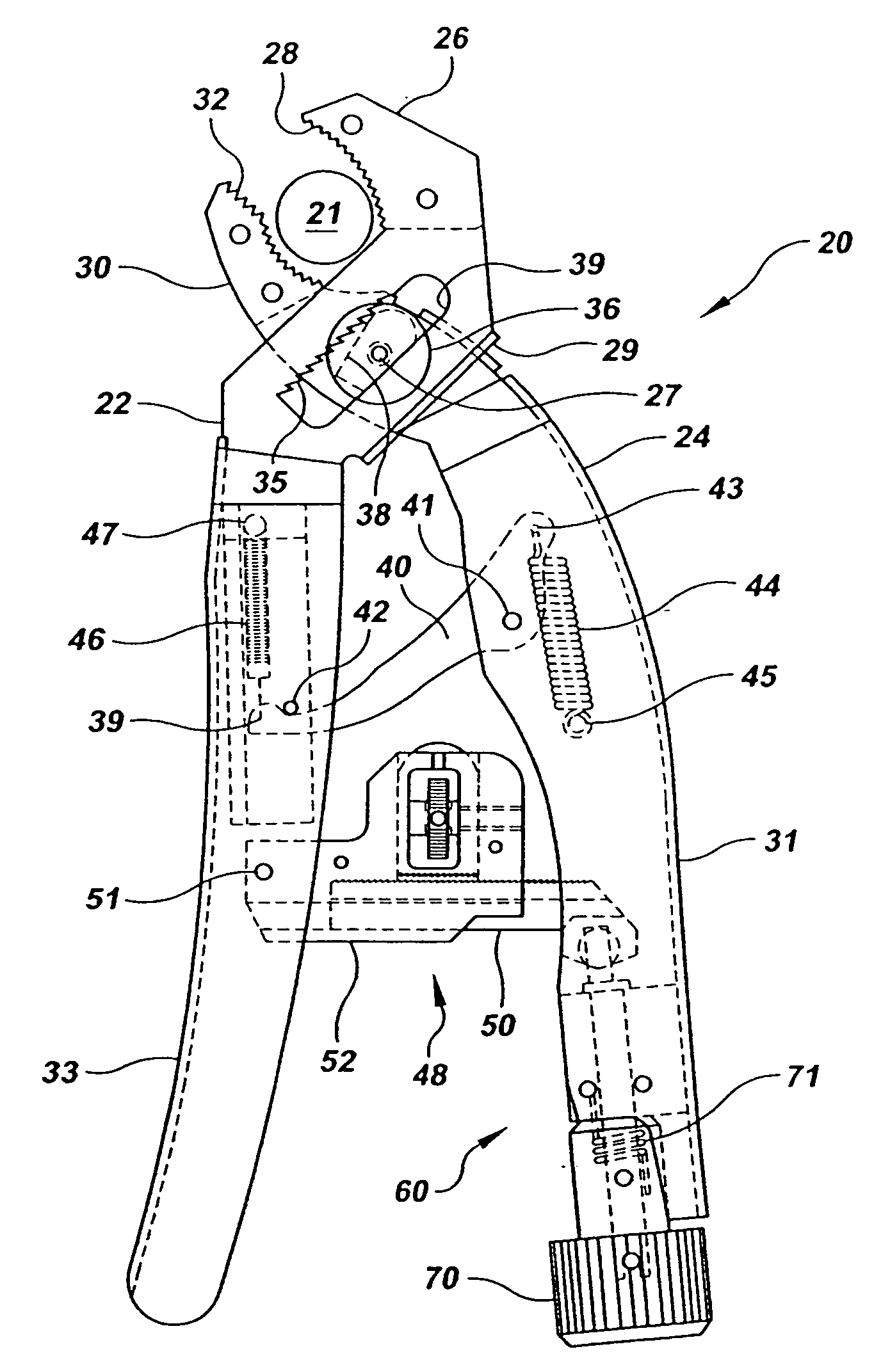
[0028] In describing the preferred embodiment of the present invention, reference will be made herein to FIGS. 1-7 of the drawings in which like numerals refer to like features of the invention.
[0029] The preferred embodiment of the present invention 20 is an improvement to prior automatic sizing pliers. Pliers 20 include separate members 22, 24 which have jaw portions at one end and handle portions at the other, and are pivotally connected at intermediate throat portions. Members 22, 24 are shown as being made of cold-formed strip steel as shown in FIGS. 3 and 4, but may be made of any other material of suitable strength, such as forged or cast steel. Member 22 has parallel jaw portions 26, including jaw teeth 28, at the end used to grip the workpiece 21 (FIG. 1), and handle portion 33 at the opposite end. Between the jaw and handle portions of member 22 are parallel throat portions, each containing slot 34 which has on its edge teeth 35. The throat of member 22 preferably includ...
PUM
Abstract
Self-adjusting pliers include first and second elongated members each having at one end a jaw portion and at the other end a handle portion, with the elongated members pivotally connected at a position intermediate the jaw and handle portions such that upon positioning the jaw portions on a workpiece and squeezing the handle portions toward each other, the jaws adjust to thickness of the workpiece as they grip the workpiece. The pliers further include a ratchetlocking mechanism between the handle portions, the locking mechanism adapted to releasably secure the handle portions upon squeezing of the handle portions toward each other and gripping of the workpiece by the jaw portions to prevent the handle portions from moving apart. A cam operated adjustor is connected to the locking mechanism to increase pressure of the jaw portions about the workpiece, after securing, by hand pressure alone.
Description
BACKGROUND OF THE INVENTION [0001] 1. Field of the Invention [0002] The present invention relates to hand-operated tools and, in particular, to pliers that may be self-adjusted for size and locked on a workpiece, and have the gripping force subsequently increased. [0003] 2. Description of Related Art [0004] It is desirable to be able to lock pliers so that the user may release his hands from the pliers while the tool remains firmly gripped about a workpiece held in the jaws. Vice grip-type pliers, as shown in U.S. Pat. Nos. 2,514,130 and 3,600,986, may be locked about a workpiece. Self-adjusting pliers have been known in the prior art, as exemplified by U.S. Pat. Nos. 4,662,252; 4,651,598; 4,802,390; 4,893,530; 5,060,543; 5,351,584 and 5,408,904. While some self-locking features have been disclosed, the design of such features has provided potential problems in manufacture and use. Moreover, whether with vice grip or self-adjusting pliers, after the jaws have been locked in place it...
Claims
Application Information
Patent Timeline
Application Date:The date an application was filed.
Publication Date:The date a patent or application was officially published.
First Publication Date:The earliest publication date of a patent with the same application number.
Issue Date:Publication date of the patent grant document.
PCT Entry Date:The Entry date of PCT National Phase.
Estimated Expiry Date:The statutory expiry date of a patent right according to the Patent Law, and it is the longest term of protection that the patent right can achieve without the termination of the patent right due to other reasons(Term extension factor has been taken into account ).
Invalid Date:Actual expiry date is based on effective date or publication date of legal transaction data of invalid patent.