
Optical disc apparatus

a technology of optical discs and optical discs, applied in the field of optical disc apparatuses, can solve the problems of inability to solve the above-described problem, the error of the automatic servo gain adjustment in relation to a distortion, and the inability to adjust the servo gain, etc., and achieve the effect of stabilizing the servo gain adjustmen

Inactive Publication Date: 2006-06-22
FUNAI ELECTRIC CO LTD
View PDF3 Cites 4 Cited by
  • Summary
  • Abstract
  • Description
  • Claims
  • Application Information

AI Technical Summary

Benefits of technology

[0009] An object of the present invention is to provide an optical disc apparatus that can stabilize servo gain adjustments.
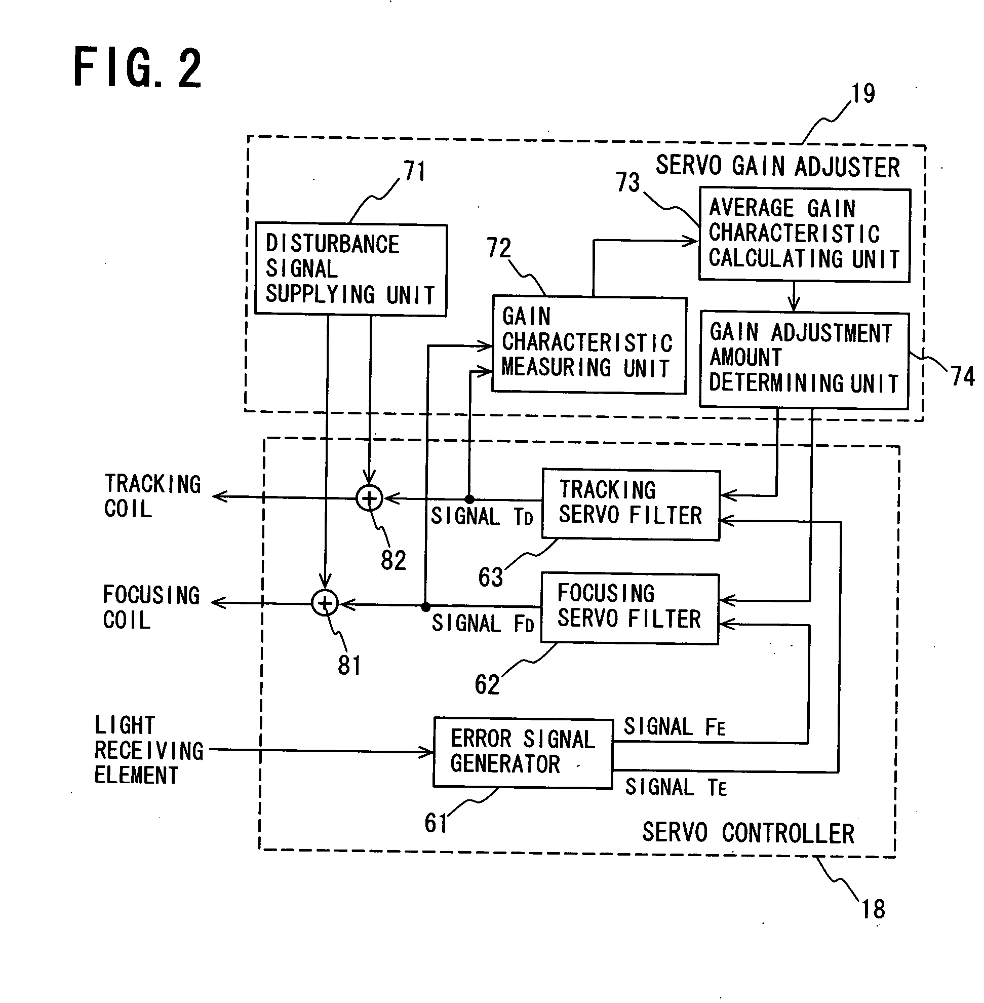
[0012] With the above configuration, the servo gain is adjusted using plural disturbance signals of different frequencies. This can prevent the servo gain from being adjusted to be undesirably high (or low) even when the frequency characteristic of the actuator has a resonance point at the same frequency as the frequency of one of the disturbance signals, thus allowing proper adjustments to the servo gain. Accordingly, the optical disc apparatus can stabilize servo gain adjustments and thus increase in performance.
[0014] With this configuration, the servo gain is adjusted based on the average of deviations of servo gain characteristics measured using plural disturbance signals of different frequencies. Accordingly, the servo gain can be adjusted more properly and more stably.
[0017] With this configuration, since about two to ten types of disturbance signals are used for adjusting the servo gain, the adjustment does not require much time. Accordingly, for example, where the servo gain is adjusted at the start of reading information from the optical disc, video and audio outputs can be produced without delay after the start of the reading.

Problems solved by technology

However, the conventional optical disc apparatus has the following problem.
As a result, a calculated gain deviation ΔG is not the “gain G1-gain G2” but “gain G3-gain G2”, which may cause an improper adjustment to the servo gain.
In other words, the conventional optical disc apparatus may cause an error in the automatic servo gain adjustment in relation to a distortion in the frequency characteristic of the actuator because it determines the servo gain adjustment amount using the disturbance signal of the single frequency.
However, the above described problem cannot be solved even if the above techniques are applied.

Method used


Image

  • Optical disc apparatus
  • Optical disc apparatus
  • Optical disc apparatus

Examples


Embodiment Construction

[0023] Referring now to the accompanying drawings, an optical disc apparatus according to one embodiment of the present invention is described. It is to be noted that the following description of preferred embodiment of the present invention has been presented for purposes of illustration and description, and is not intended to be exhaustive or to limit the present invention to the precise form disclosed.

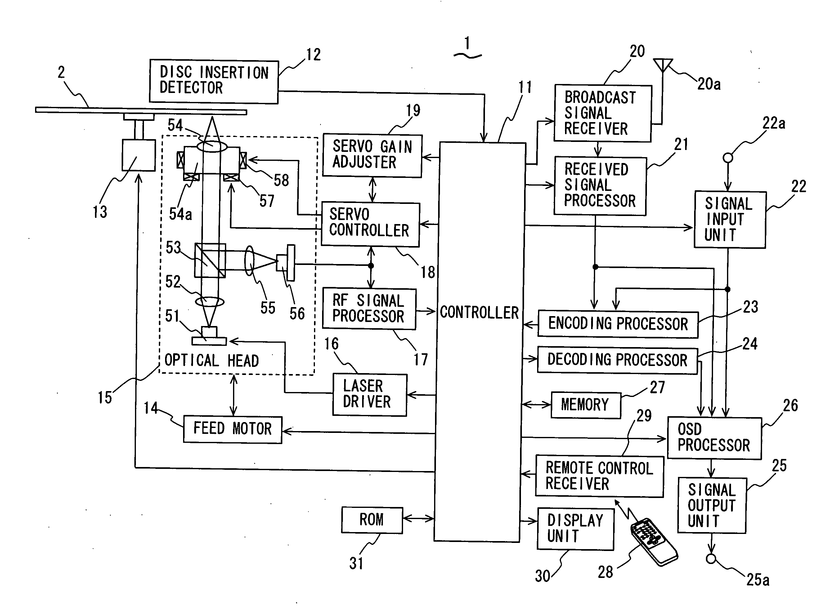
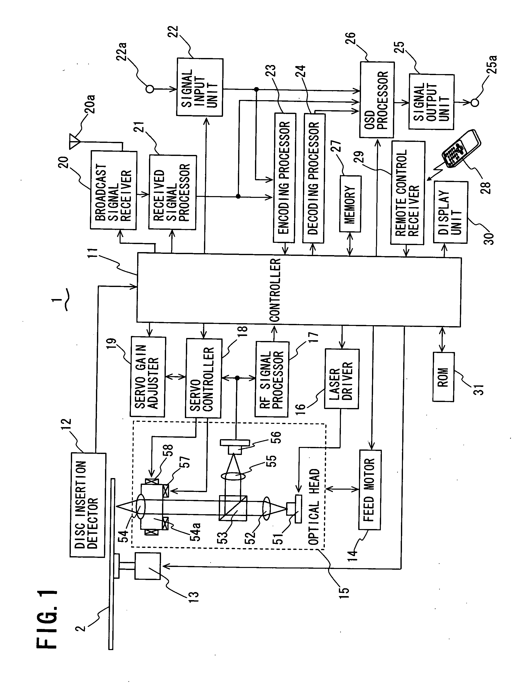
[0024]FIG. 1 shows the configuration of the optical disc apparatus 1 according to this embodiment. The optical disc apparatus 1 is an apparatus that records and / or reproduces information such as, for example, video, audio, and text on an optical disc 2 such as a CD, a DVD, or the like having recording tracks formed concentrically or spirally thereon.

[0025] The optical disc apparatus 1 comprises a controller 11 including a central processing unit (CPU) for controlling each component in the optical disc apparatus 1, a disc insertion detector 12, a spindle motor 13, a feed motor 14, ...


PUM

PropertyMeasurementUnit
frequenciesaaaaaaaaaa
cut-off frequencyaaaaaaaaaa
frequencyaaaaaaaaaa

Abstract

An optical disc apparatus includes a servo gain adjuster, which includes a disturbance signal supplying unit that generates plural disturbance signals of different frequencies and supplies them in sequence to a servo loop, a gain characteristic measuring unit that measures a deviation of a servo gain characteristic of the servo loop based on each disturbance signal passed through the servo loop, an average gain characteristic calculating unit that calculates the average of deviations of plural servo gain characteristics measured by the gain characteristic measuring unit in response to the plural disturbance signals supplied from the disturbance signal supplying unit, and a gain adjustment amount determining unit that determines an amount of adjustment to the servo gain of the servo loop based on the average of the deviations of the servo gain characteristics that is calculated by the average gain characteristic calculating unit. The optical disc apparatus can provide stable adjustments to the servo gain of the servo control that causes the focused spot of light to follow the recording track of an optical disc.

Description

BACKGROUND OF THE INVENTION [0001] 1. Field of the Invention [0002] The present invention relates to an optical disc apparatus that records and / or reproduces information on an optical disc such as a compact disc (CD), a digital versatile disc (DVD), or the like. [0003] 2. Description of the Related Art [0004] Optical disc apparatus are typically configured to focus light emitted from a light emitting element through an objective lens onto an optical disc and receive the light reflected from the optical disc through the objective lens at a light receiving element while rotating the optical disc by a spindle motor, and read information recorded on the optical disc based on output signals from the light receiving element. Further, when reading information from an optical disc, the optical disc apparatus use a servo controller thereof to drive an actuator and thereby move the objective lens based on output signals from the light receiving element so that the spot of light focused onto t...

Claims


Application Information

Patent Timeline
Patent Type & Authority Applications(United States)
IPC IPC(8): G11B7/00
CPCG11B7/0941
Inventor INADA, TSUTOMU
Owner FUNAI ELECTRIC CO LTD
Learn More