Brush, commutator, and commutator device
- Summary
- Abstract
- Description
- Claims
- Application Information
AI Technical Summary
Benefits of technology
Problems solved by technology
Method used
Image
Examples
first embodiment
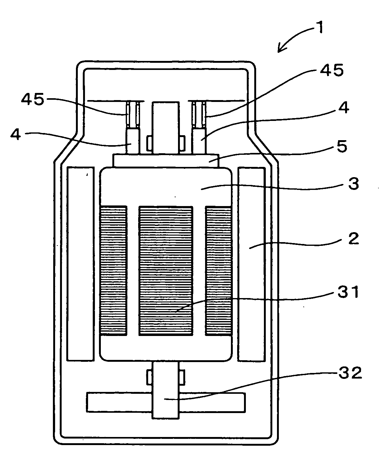
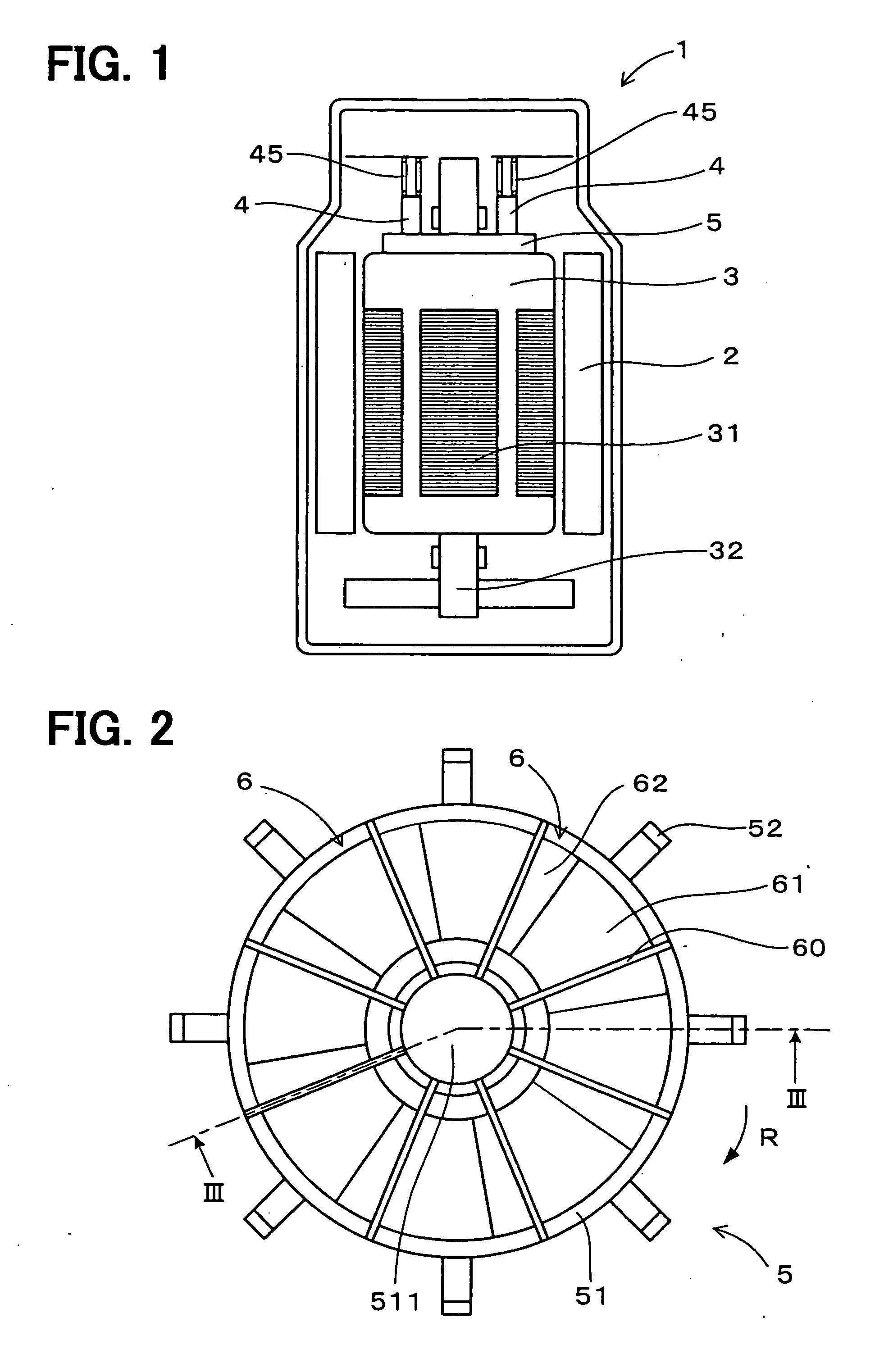
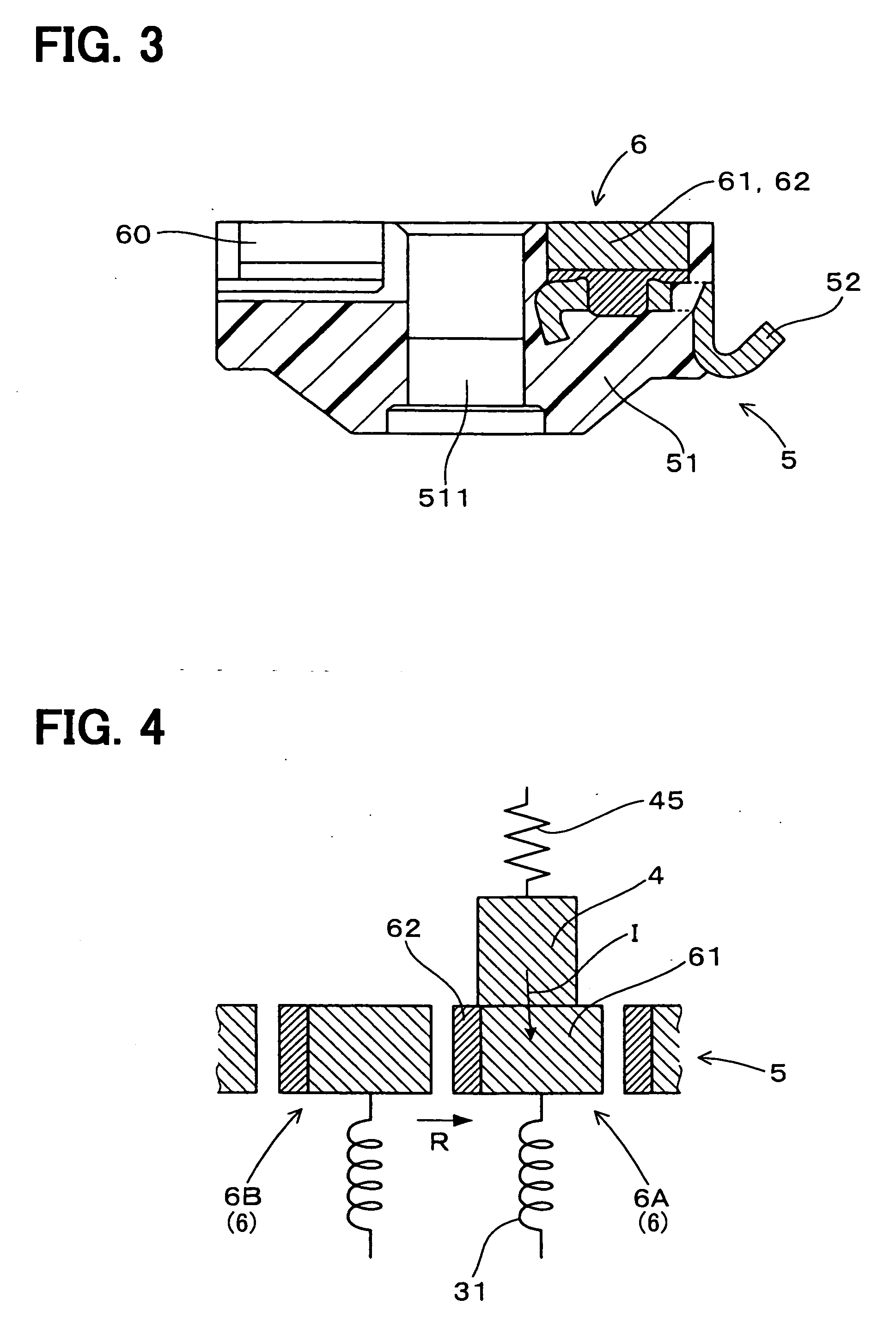
[0034] Referring to FIGS. 1 and 2, a brush 4 and a commutator 5 of the first embodiment are used in a d.c. motor 1 as a rotary electric machine. The d.c. motor 1 has a stator 2 provided with permanent magnets or a field winding, and a rotor 3 provided with a plurality of armature windings 31. A pair of brushes 4 is arranged on the stator 2 for supplying direct current. The commutator 5 is connected to a rotor shaft 32 of the rotor 3. The commutator 5 has a plurality of commutator segments 6 that are connected to the armature windings 31, respectively, as shown in FIGS. 4 and 5.
[0035] As shown in FIGS. 2 and 3, the commutator 5 is a flat-type, and is located on an axial end surface of the rotor 3 to make contact with the brushes 4. Specifically, the commutator segments 6 are mounted on a resinous body member 51 having a disk shape. The commutator segments 6 are arranged to extend from a center 511 of the body member 51 in a radial direction. Further, clearances 60 are defined betwee...
second embodiment
[0053] Referring to FIGS. 6 and 7, a d.c. motor 1 of the second embodiment has the pair of brushes 4 each of which is constructed of two resistive layers and the commutator 5 having a plurality of commutator segments 6 each of which is constructed of a single layer. Specifically, each of the brushes 4 has a low-resistive layer 41 made of a low-resistive material and a high-resistive layer 42 made of a high-resistive material having a specific resistance higher than that of the low-resistive material.
[0054] The low-resistive material contains a carbonic material and a binder. The high-resistive material contains a carbonic material, a binder, and boron nitride (BN) as an inorganic substance. Here, a mixing ratio of the boron nitride is higher than 20 wt % against a total weight of the high-resistive material.
[0055] The d.c. motor 1 of the second embodiment is used in a fuel pump for a vehicle, and a rotor 3 of the d.c. motor 1 is rotated in one direction R. As shown in FIGS. 6 and ...
third embodiment
[0067] Hereafter, an example of the method of producing the commutator 5 of the first embodiment and the brushes 4 of the second embodiment will be described.
[0068] The commutator segment 6 and the brushes 4 having two resistive layers 41, 42, 61, 62 are produed as follows.
[0069] First, as a method of producing the high-resistive material, carbonic powder such as graphite (e.g. 25 wt % natural graphite powder having an average particle diameter of 30 μm) and inorganic powder such as boron nitride (e.g. 75 wt % hexagonal boron nitride powder having an average particle diameter of 10 μm) are mixed into each other. Then, novolac phenol aldehyde resin (e.g. 15 weight ratio), which is dissolved in methanol solution (e.g. 30 weight ratio), is added in the mixed powder (100 weight ratio), as the binder. Further, the mixture is kneaded by a mixer, and to thereby produce the mixed material.
[0070] After, the mixed material is dried in a drier to evaporate methanol. Thus, a block of the hig...
PUM
 Abstract
Description
Claims
Application Information
 - R&D
- Intellectual Property
- Life Sciences
- Materials
- Tech Scout
- Unparalleled Data Quality
- Higher Quality Content
- 60% Fewer Hallucinations
Browse by: Latest US Patents, China's latest patents, Technical Efficacy Thesaurus, Application Domain, Technology Topic, Popular Technical Reports.
© 2025 PatSnap. All rights reserved.Legal|Privacy policy|Modern Slavery Act Transparency Statement|Sitemap|About US| Contact US: help@patsnap.com


