
Reactant feed for nested stamped plates for a compact fuel cell

a fuel cell and reactant technology, applied in the field of reactant feed for compact fuel cells, can solve the problems of adversely affecting the flow rate and performance of the stack, relatively high cost of meas, etc., and achieve the effect of reducing the thickness of the stack and increasing the distance between adjacent meas

Active Publication Date: 2006-06-15
GM GLOBAL TECH OPERATIONS LLC
View PDF4 Cites 95 Cited by
  • Summary
  • Abstract
  • Description
  • Claims
  • Application Information

AI Technical Summary

Benefits of technology

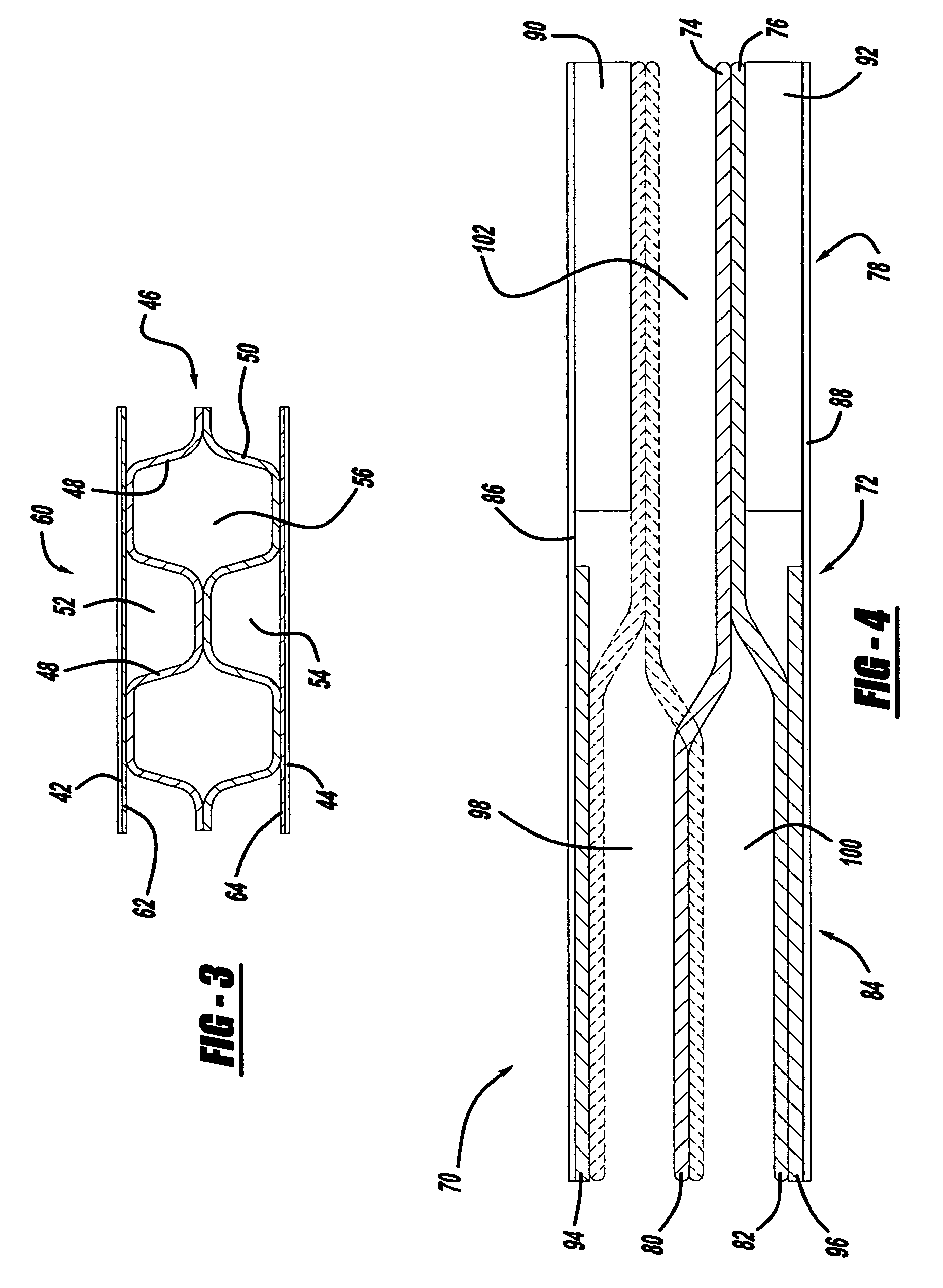
[0014] In accordance with the teachings of the present invention, a fuel cell in a fuel cell stack is disclosed that provides a transition from nested bipolar plates in the active region of the stack to non-nested bipolar plates in the inactive feed regions of the stack without giving up the reduced stack thickness provided by the nested plates or changing the size of the flow channels. Particularly, the diffusion media layers in the fuel cells of the stack are removed in the inactive feed regions where the bipolar plates are non-nested so that the volume necessary to maintain the size of the flow channels is provided without the need to increase the distance between adjacent MEAs. Additionally, the membrane of the MEAs would not be catalyzed in the inactive regions. A thin shim can be provided between the membranes and the plates in the inactive regions to support the membrane where the diffusion media layer has been removed to prevent the membrane from intruding into the flow channels and blocking the reactive flow.

Problems solved by technology

MEAs are relatively expensive to manufacture and require certain conditions for effective operation.
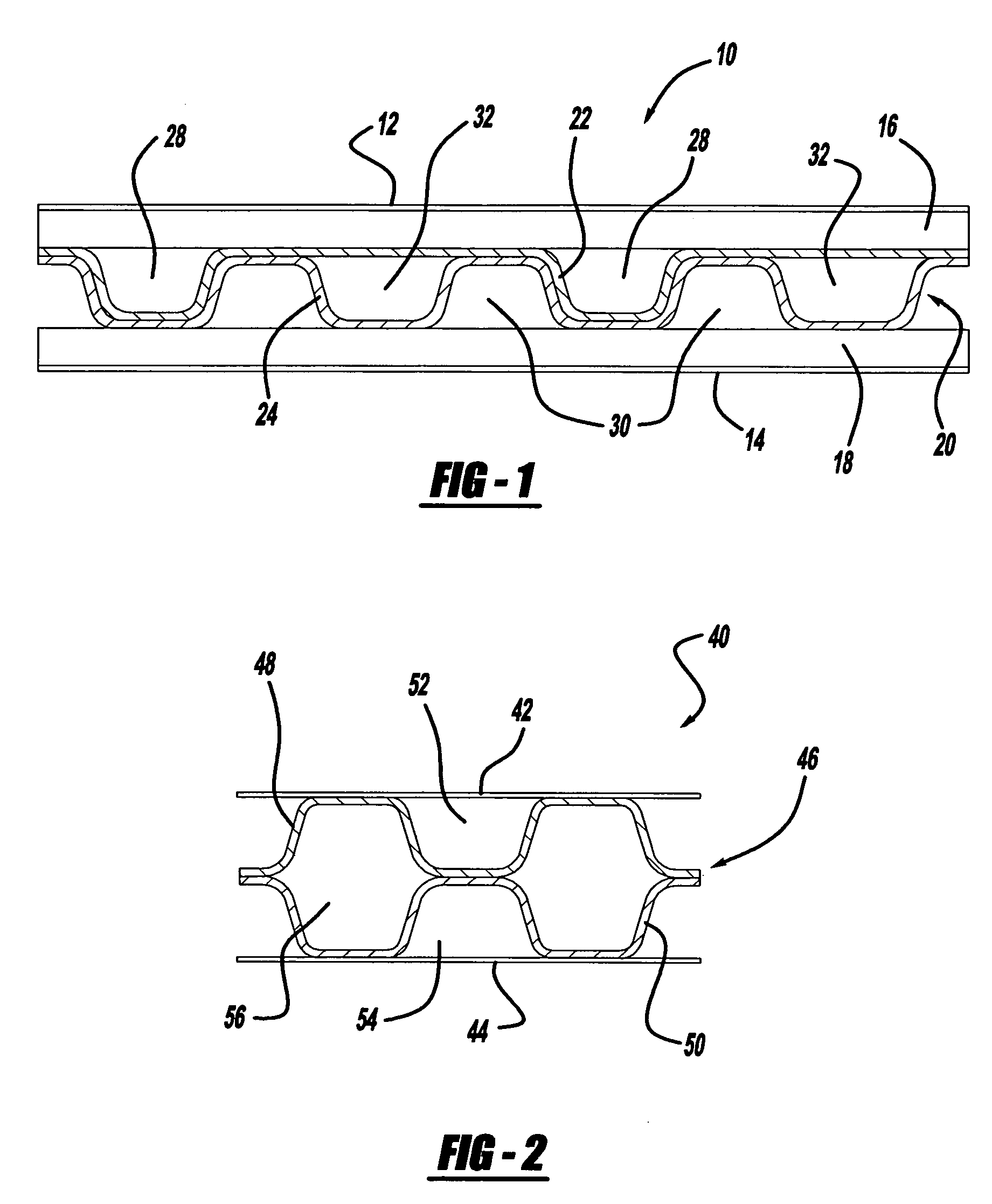
However, such a reduction in the size of the channels 28, 30 and 32 would cause a pressure drop across the channels that would adversely affect the flow rate and performance of the stack 10.

Method used


Image

  • Reactant feed for nested stamped plates for a compact fuel cell
  • Reactant feed for nested stamped plates for a compact fuel cell
  • Reactant feed for nested stamped plates for a compact fuel cell

Examples


Embodiment Construction

[0022] The following discussion of the embodiments of the invention directed to a fuel cell design is merely exemplary in nature, and is in no way intended to limit the invention or its applications or uses.

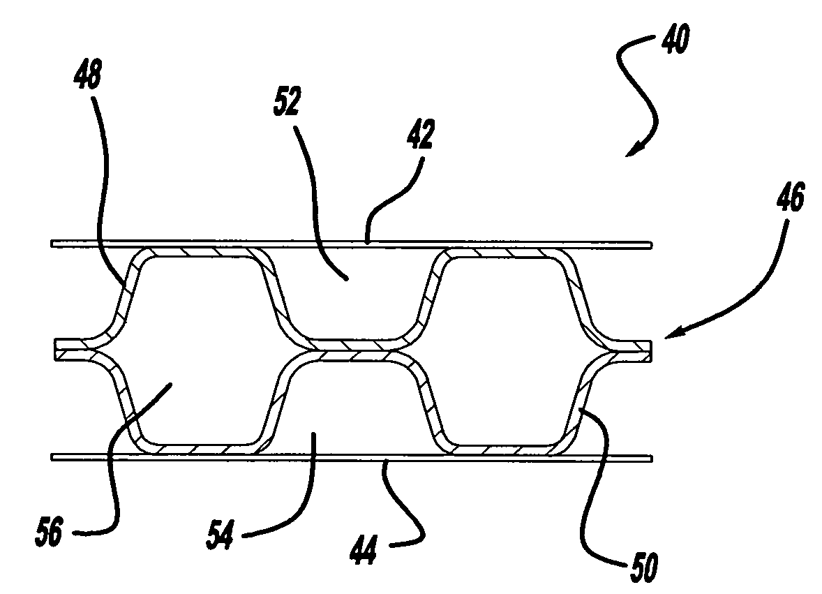
[0023] According to the present invention, a fuel cell design is described that includes nested stamped bipolar plates in an active region of the fuel cell and non-nested stamped bipolar plates in an inactive feed region of the fuel cell. FIG. 2 is a partial cross-sectional view through an inactive feed region of a fuel cell stack 40. The stack 40 includes adjacent membranes 42 and 44 that are part of two adjacent MEAs in the stack 40. The fuel cell stack 40 also includes a bipolar plate assembly 46 having two stamped non-nested bipolar plates 48 and 50. The plates 48 and 50 are stamped so that they define anode flow channels 52, cathode flow channels 54 and coolant flow channels 56.

[0024] It is necessary that the plates 48 and 50 be non-nested in the feed regions of the stack ...


PUM


Abstract

A fuel cell in a fuel cell stack that provides a transition from nested bipolar plates in the active region of the stack to non-nested bipolar plates in the inactive regions of the stack without giving up the reduced stack thickness provided by the nested plates or changing the size of the flow channels. Particularly, the diffusion media layers in the fuel cells are removed in the inactive regions where the bipolar plates are non-nested so that the volume necessary to maintain the size of the flow channels is provided without the need to increase the distance between adjacent MEAs. A thin shim can be provided between the membranes and the plates in the inactive regions to support the membrane where the diffusion media layer has been removed to prevent the membrane from intruding into the flow channels and blocking the reactive flow.

Description

BACKGROUND OF THE INVENTION [0001] 1. Field of the Invention [0002] This invention relates generally to a fuel cell for a fuel cell stack and, more particularly, to a fuel cell for a fuel cell stack, where the fuel cell includes nested flow channels in an active region of the fuel cell and non-nested flow channels in inactive feed regions of the fuel cell, and where the diffusion media layers in the cells are removed in the inactive feed regions to provide more space for the non-nested channels. [0003] 2. Discussion of the Related Art [0004] Hydrogen is an attractive fuel because it is clean and can be used to efficiently produce electricity in a fuel cell. The automotive industry expends significant resources in the development of hydrogen fuel cells as a source of power for vehicles. Such vehicles would be more efficient and generate fewer emissions than today's vehicles employing internal combustion engines. [0005] A hydrogen fuel cell is an electrochemical device that includes a...

Claims


Application Information

Patent Timeline
IPC IPC(8): H01M8/00H01M8/04H01M4/00H01M2/02H01M4/86
CPCH01M8/0254H01M8/0258H01M8/0265H01M8/0267H01M8/04089H01M2250/20Y02E60/50Y02T90/32Y02T90/40H01M8/2483H01M8/241
Inventor GOEBEL, STEVEN G.ROCK, JEFFREY A.
Owner GM GLOBAL TECH OPERATIONS LLC
Learn More