Front fork
a front fork and fork body technology, applied in shock absorbers, cycle equipment, transportation and packaging, etc., can solve the problems of conventional front forks having a limit of building up pressure, oil leakage from the fork body, etc., to improve the riding comfort of the vehicle and reduce the change of vehicle attitud
- Summary
- Abstract
- Description
- Claims
- Application Information
AI Technical Summary
Benefits of technology
Problems solved by technology
Method used
Image
Examples
first preferred embodiment
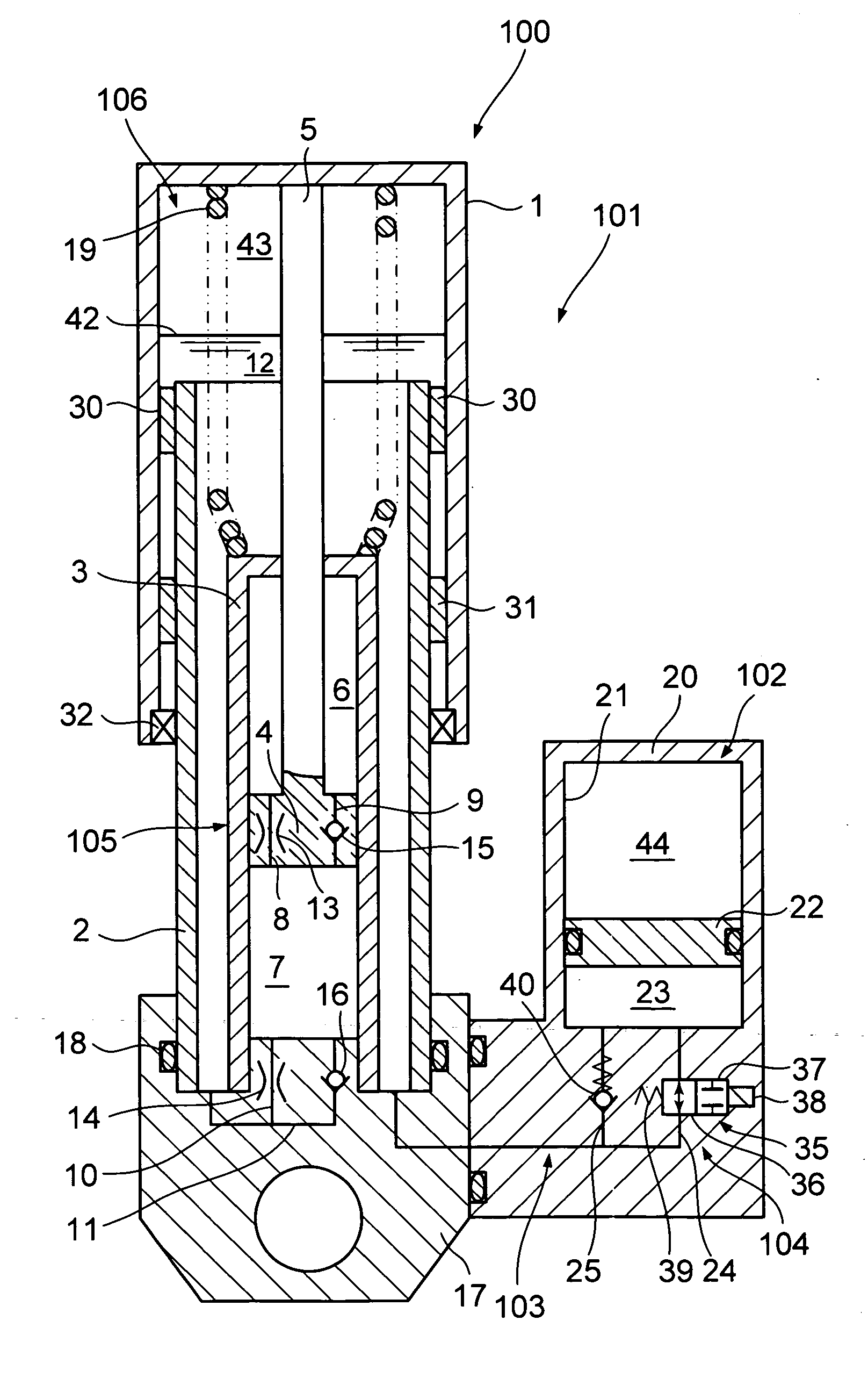
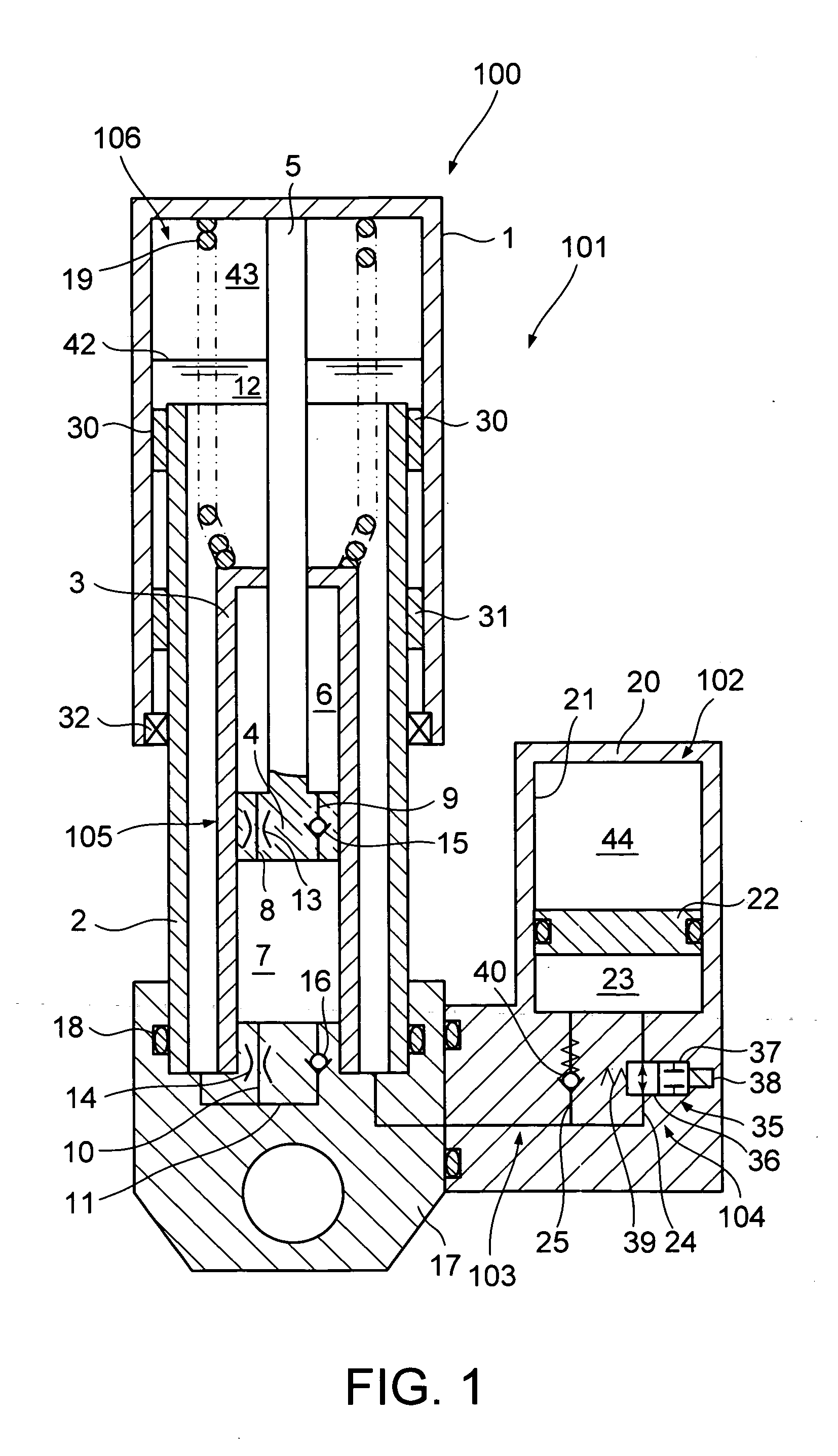
[0018] A front fork 100 according to a first preferred embodiment of the present invention will be first described with reference to FIG. 1. FIG. 1 is a schematic view showing the front fork 100.
[0019] The front fork 100 is interposed between a vehicle body and a front-wheel axle of a two-wheeled vehicle and functions as a hydraulic shock absorber that absorbs road vibrations exerted on the front wheel to restrain a change in vehicle attitude. The front fork 100 is equipped with a fork body 101 performing an expansion and contraction operation with a reaction force against a change in vehicle attitude, a reservoir tank 102 provided outside the fork body 101 and generating a reaction force when the fork body 101 performs the expansion and contraction operation, and a flow adjusting apparatus 104 placed on a flow path 103 for communication between the fork body 101 and the reservoir tank 102 and adjusting the flow of hydraulic oil.
[0020] The fork body 101 has a reservoir chamber 106...
second preferred embodiment
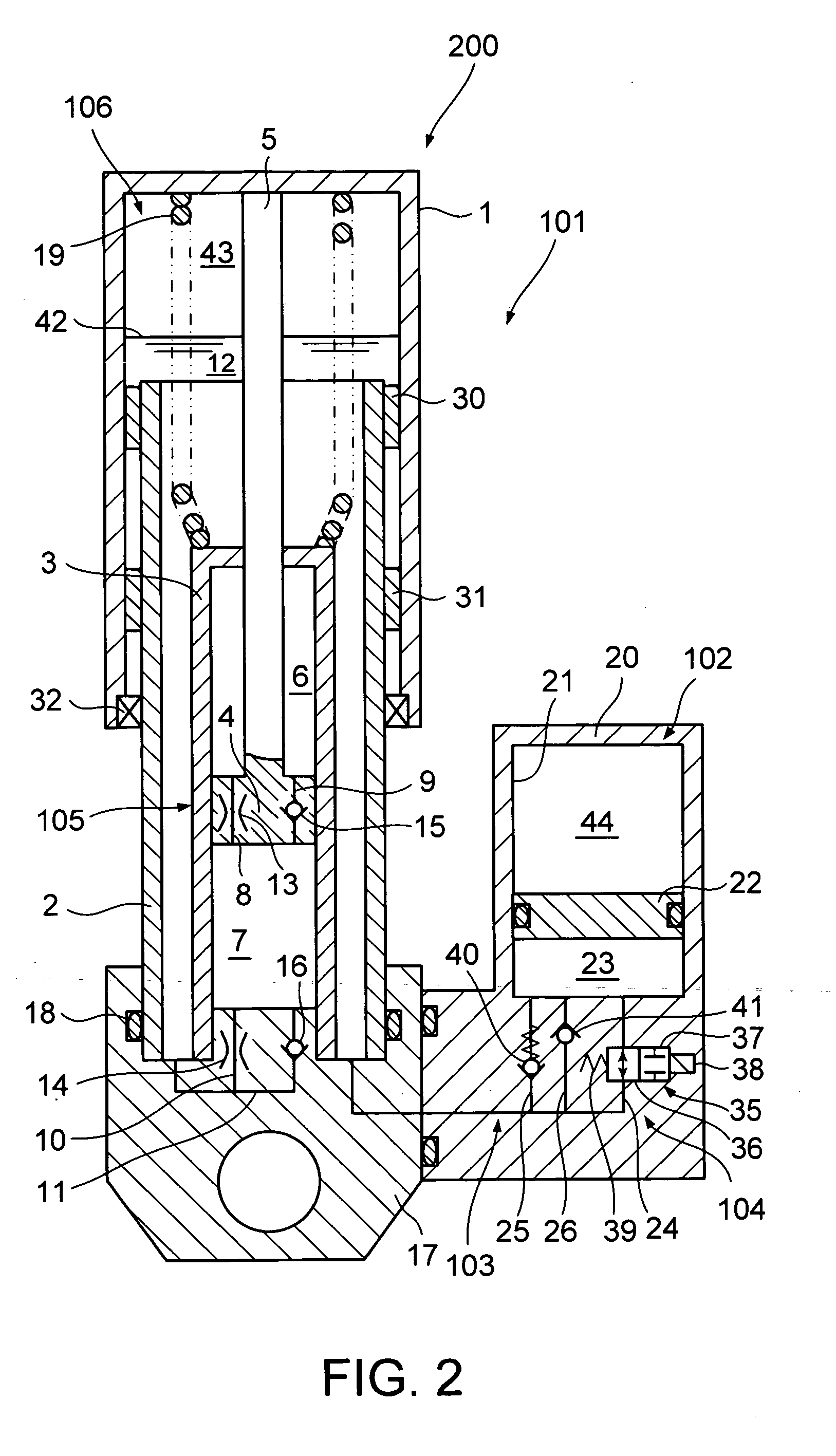
[0065] A front fork 200 according to a second preferred embodiment of the present invention is described with reference to FIG. 2. FIG. 2 is a schematic view showing the front fork 200. Note that the same structure as that in the first preferred embodiment is designated by the same reference numerals and the description is omitted.
[0066] Differences between the front fork 200 of the second preferred embodiment and the front fork 100 of the first preferred embodiment are that the front fork 200 is equipped with an on-off valve 35 and a relief valve 40 as the flow adjustment apparatus 104 for adjusting a flow of hydraulic oil between an oil chamber 12 of a front fork 101 and an oil chamber 23 of a reservoir tank 102, and further a check valve 41 that accepts only a flow of hydraulic oil from the reservoir tank 102 toward a reservoir chamber 106 of the fork body 101.
[0067] The check valve 41 is provided in a passage 26 communicating with a passage 24 and bypassing the on-off valve 35...
third preferred embodiment
[0077] A front fork 300 according to a third preferred embodiment of the present invention is described with reference to FIG. 3. FIG. 3 is a diagram conceptually illustrating the front fork 300. Note that the same structure as that in the first and second preferred embodiments is designated by the same reference numerals and the description is omitted.
[0078] Differences between the front fork 300 of the third preferred embodiment and the front fork 200 of the second preferred embodiment lie in that the front fork 200 has the outer tube 1 connected to the side of the vehicle body and the inner tube 2 connected to the side of the axle, but the front fork 300 has an outer tube 51 connected to a side of an axle and an inner tube 52 connected to the side of the vehicle body, and in the structure of a damper portion.
[0079] A damper portion 305 in the front fork 300 includes a hollow pipe 61 standing in an axial core portion of the bottom of the outer tube 51, a piston 62 provided on th...
PUM
 Abstract
Description
Claims
Application Information
 - R&D
- Intellectual Property
- Life Sciences
- Materials
- Tech Scout
- Unparalleled Data Quality
- Higher Quality Content
- 60% Fewer Hallucinations
Browse by: Latest US Patents, China's latest patents, Technical Efficacy Thesaurus, Application Domain, Technology Topic, Popular Technical Reports.
© 2025 PatSnap. All rights reserved.Legal|Privacy policy|Modern Slavery Act Transparency Statement|Sitemap|About US| Contact US: help@patsnap.com


