
Optical fiber with micro-structured cladding

a technology of optical fiber and microstructure, applied in the field of optical waveguides, can solve the problems of disadvantages or drawbacks, high cost and/or difficult matter of microstructure formation, etc., and achieve the effect of high numerical apertur

Active Publication Date: 2006-06-08
NUFERN
View PDF1 Cites 35 Cited by
  • Summary
  • Abstract
  • Description
  • Claims
  • Application Information

AI Technical Summary

Benefits of technology

[0014] As can be seen from the following description, in certain embodiments the invention can provide an improved method of making an optical fiber with a micro-structured cladding. The invention can also provide, in certain embodiments, an improved double-clad fiber wherein at least two of the cladding comprise a glass. One of the claddings, such as the inner or pump cladding, can have high numerical aperture. “Double-clad”, as used herein, means a fiber having at least two claddings, and can include a fiber having more than two claddings, such as, for example, a triple-clad fiber. As used herein the term “optical”, such as is used in the term “optical waveguide” or “optical fiber”, is used to mean a waveguide or fiber, as the case may be, for use with electromagnetic energy, as is well understood by those of ordinary skill in the art. It is inappropriate for the term “optical” to be limited to the range of visible wavelengths, as is readily appreciated by one of ordinary skill, but perhaps not appreciated by one not of ordinary skill inclined to inappropriately rely solely on a layman's dictionary, which may restrict the term “optical” to visible wavelengths.

Problems solved by technology

In the known fibers having selected cladding designs, such as, for example, micro-structured claddings, the formation of the micro-structure can be an expensive and / or difficult matter, and usually is achieved by the making of holes in the cladding material of a preform from which the fiber is drawn, and these holes become extended over great lengths in the drawing of the fiber from the preform.
Although one or more of the known optical fibers may have had certain features that represented or were thought to represent an advance in the art when introduced, disadvantages or drawbacks remain, particularly with regard to certain applications.

Method used


Image

  • Optical fiber with micro-structured cladding
  • Optical fiber with micro-structured cladding

Examples


Embodiment Construction

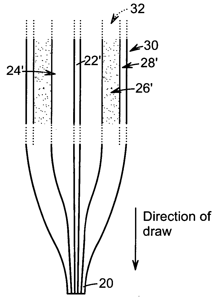
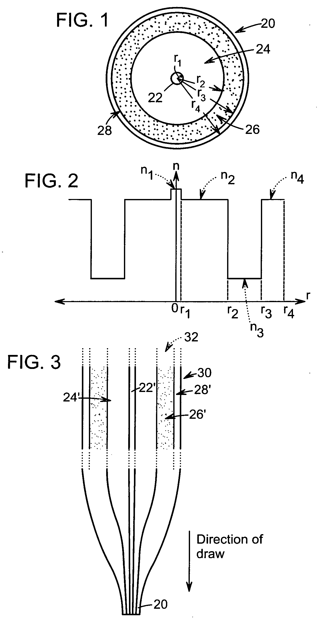
[0021] Optical fibers having a region (e.g., a cladding or a core) having an increased numerical aperture can be useful in certain applications, such as, for example, high-power fiber lasers or amplifiers. For example, in a double-clad fiber, it is often advantageous for the inner or pump cladding to have a high numerical aperture. It can also be desirable for the core of a fiber to have a higher numerical aperture. One approach to raise the numerical aperture of a region is to raise the index of refraction of the host material (e.g., silica) of a region of an optical fiber by doping the region with an index raising dopant (e.g., germanium). Where the core of a fiber is doped, the cladding can, for example, consist or consist essentially of silica or can comprise silica that includes a dopant, such as, for example, one on or more of germanium, silica or phosphorus. Realization of fibers of high numerical aperture by raising the index of a region can be limited by the processing diff...


PUM

PropertyMeasurementUnit
lengthaaaaaaaaaa
lengthaaaaaaaaaa
lengthaaaaaaaaaa

Abstract

An optical fiber having a length can include a core and at least one cladding disposed about the core, where the one cladding can comprise at least first volumetric regions having a first refractive index n1 and second volumetric regions having a second refractive index n2, different from n1, and the first and second volumetric regions in any cross-section taken through the fiber can be randomly intermingled with one another, where the random intermingling of the first and second volumetric regions changes with changes in the location of the cross-section along the length of the fiber.

Description

FIELD OF THE INVENTION [0001] The present invention relates to optical waveguides, and more particularly to optical fibers, such as, for example, an optical fiber having a micro-structured region. BACKGROUND OF THE INVENTION [0002] Optical fibers with selected claddings (e.g., micro-structured claddings) are well known, for example from U.S. Pat. Nos. 5,907,652, 6,522,820, 6,594,429, 6,766,088 and 6,775,450. In the fibers described in one or more of these patents an apparent aim is to introduce some regions of air or other selected refractive index into the involved cladding to give it a different (e.g., lower) effective index than would otherwise be the case and thereby give the fiber characteristics, such as increased power handling ability, attractive for some applications. [0003] In the known fibers having selected cladding designs, such as, for example, micro-structured claddings, the formation of the micro-structure can be an expensive and / or difficult matter, and usually is a...

Claims


Application Information

Patent Timeline
Patent Type & Authority Applications(United States)
IPC IPC(8): G02B6/032
CPCC03B37/02754C03B37/02763C03B37/02781C03B37/0279C03B2201/31C03B2201/60C03B2201/70C03B2201/80C03B2201/86C03B2203/14C03B2203/18C03B2203/42G02B6/02357G02B6/032G02B6/0365
Inventor MANYAM, UPENDRA H.TANKALA, KANISHKA
Owner NUFERN
Learn More