
Rugged fiber optic array

Inactive Publication Date: 2006-06-08
SABEUS PHOTONICS
View PDF3 Cites 69 Cited by
  • Summary
  • Abstract
  • Description
  • Claims
  • Application Information

AI Technical Summary

Benefits of technology

[0017] The present invention eliminates the requirement for rigid, air-backed mandrels for the fiber optic hydrophones. Instead, long cylindrical segments of a continuously flexible elastomer form the base of the hydrophone structure. The optical fiber is wound onto the one-piece segments that are completely free of the rigid mandrel / flexible link interfaces and their associated problems. Compliance is provided to hydrophone through the use of voided plastic microspheres dispersed within the elastomer substrate. The hardness of the microsphere containing elastomer is controlled to meet the required acoustic sensitivity and the acoustic sensitivity versus depth requirements of a particular application.
[0018] One advantage of using an elastomer substrate is that the dynamic properties of the elastomer, such as, for example, bulk modulus and Poisson's ratio, may be altered as necessary to tailor the mechanical response of the sensor for an application. Such tailoring is useful, for example, to achieve mechanical roll-off of undesired (that, is, out of band) frequency response. The ability to suppress selected frequency ranges provides for limiting the bandwidth of the fiber optic sensors, reducing demands on the demodulation electronics, which historically require, using prior art sensors, sample rates that are orders of magnitude higher than that required to satisfy Nyquist criteria in order to maintain large dynamic ranges.
[0021] In other aspects of the present invention, the outer surface of the hydrophone may be formed from a tough, abrasion resistant elastomeric cover, which provides turbulent boundary layer noise rejection. In one embodiment, microspheres may be added to the low shear polymer and / or the elastomeric cover as needed to adjust buoyancy of the hydrophone array. This embodiment is particularly advantageous in that the hydrophone may be used as is, that is, the fiber optic hydrophone may be towed without needing to be encased within a fluid filled tube, as is typical for fiber optic hydrophone arrays presently used.

Problems solved by technology

Because these additional circuits or electronics are necessarily located underwater, the circuits and electronics are exposed to harsh conditions, such as extreme pressure due to the depth the hydrophone is deployed, or water leakage into the hydrophone housing.
Because such repairs are costly and time consuming, and may require the use of specialized vessels and equipment to retrieve the damaged hydrophones, there is a need for a more robust acoustic sensor.
Acoustic pressure waves present in the water dynamically strain the fiber, resulting in a shift in the phase of the light transmitted in the optical fiber.
One disadvantage of presently available fiber optic sensors is that the fiber generally is wrapped around discrete, hollow mandrels that are stiff enough to withstand the hydrostatic pressure requirements of deploying hydrophones under water, yet are compliant enough so that the acoustic pressure waves in the water can dynamically deform the mandrel, thereby straining the optical fiber resulting in a phase shift of the light transmitted through the fiber.
In general the mandrels used in presently available fiber optic sensors are stiff and unbendable.
This is disadvantageous in that it is useful to be able to manufacture fiber optic sensor arrays in long continuous sections, and to store such arrays on circular drums, from which the fiber optic sensor array may be deployed and retrieved, and such long sections need to be flexible.
A considerable amount of labor must be used to assemble the optic fiber wrapped on the air-backed mandrels into interferometers.
This laborious process includes preparing the optical fiber, splicing and recoating the optical fiber, dressing the optical fiber, mechanically assembling the pressure vessels, and sealing and testing the vessels and optical fiber to ensure that the resulting assembly is water tight and functions as desired.
In addition, array strength members and extra optical fibers often must be placed along the outer surface of the continuous section, leading to optical fiber damage during reeling / unreeling operations as a result of friction, bending, crushing, and the like.
This is disadvantageous in acoustic frequency ranges that contain unwanted acoustic signals, such as noise caused by fish, whales or other sound source, whose presence limits the dynamic range of the overall system unless very high sample rates are used by the system electronics to interrogate the sensors to allow signal analysis and canceling of the noise.
Such construction may be disadvantageous because such liquid-filled fiber optic sensor arrays are susceptible to puncture during deployment and reeling operations as well as during normal operation, and leakage of the fluid typically results in failure of the array.
Moreover, where a fluid such as kerosene or kerosene-like liquids or other possibly environmentally hazardous material is used, leakage of the fluid can contribute to unwanted pollution.

Method used


Image

  • Rugged fiber optic array
  • Rugged fiber optic array
  • Rugged fiber optic array

Examples


Embodiment Construction

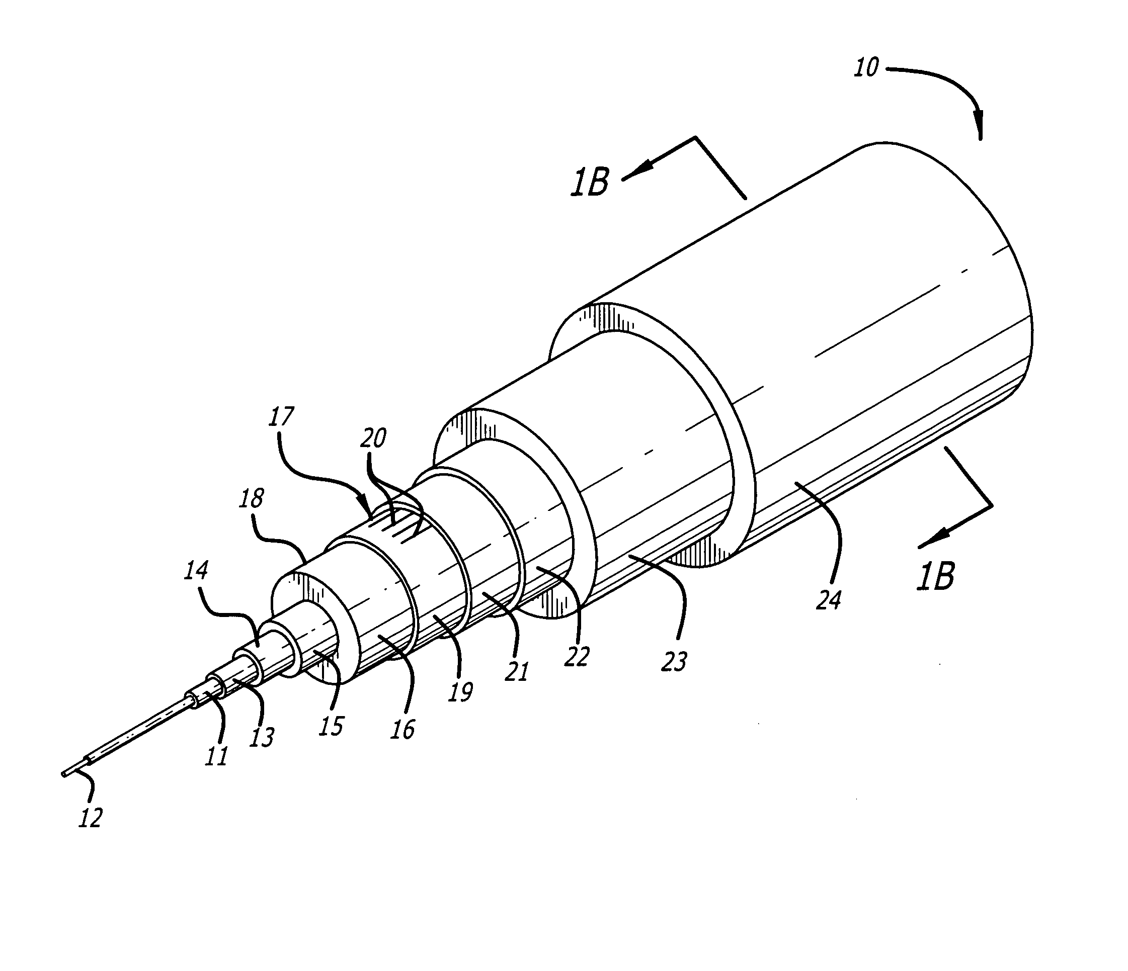
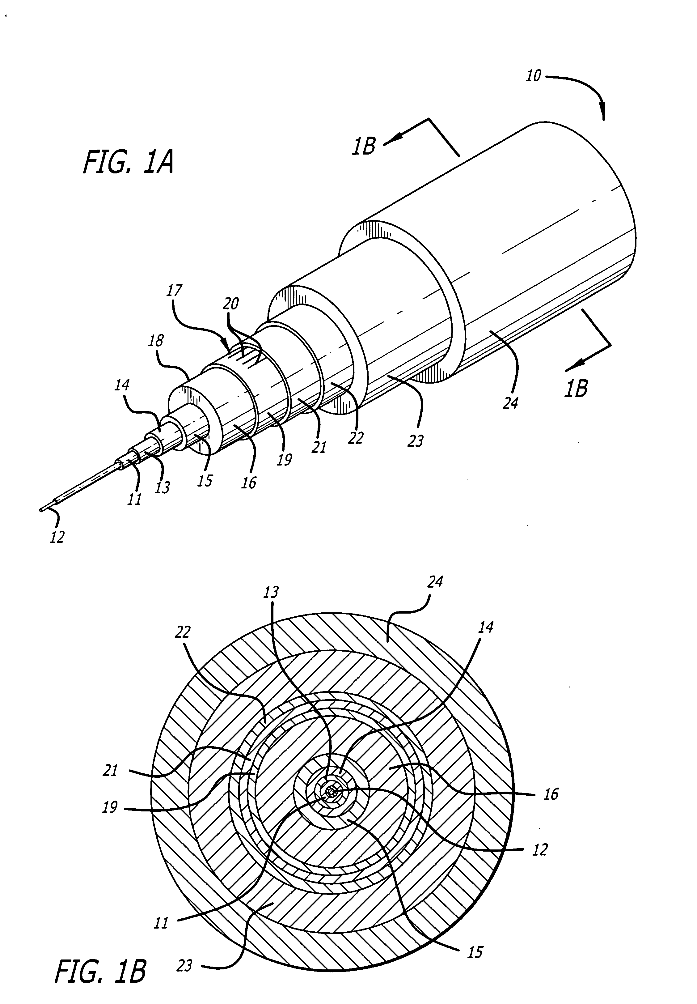
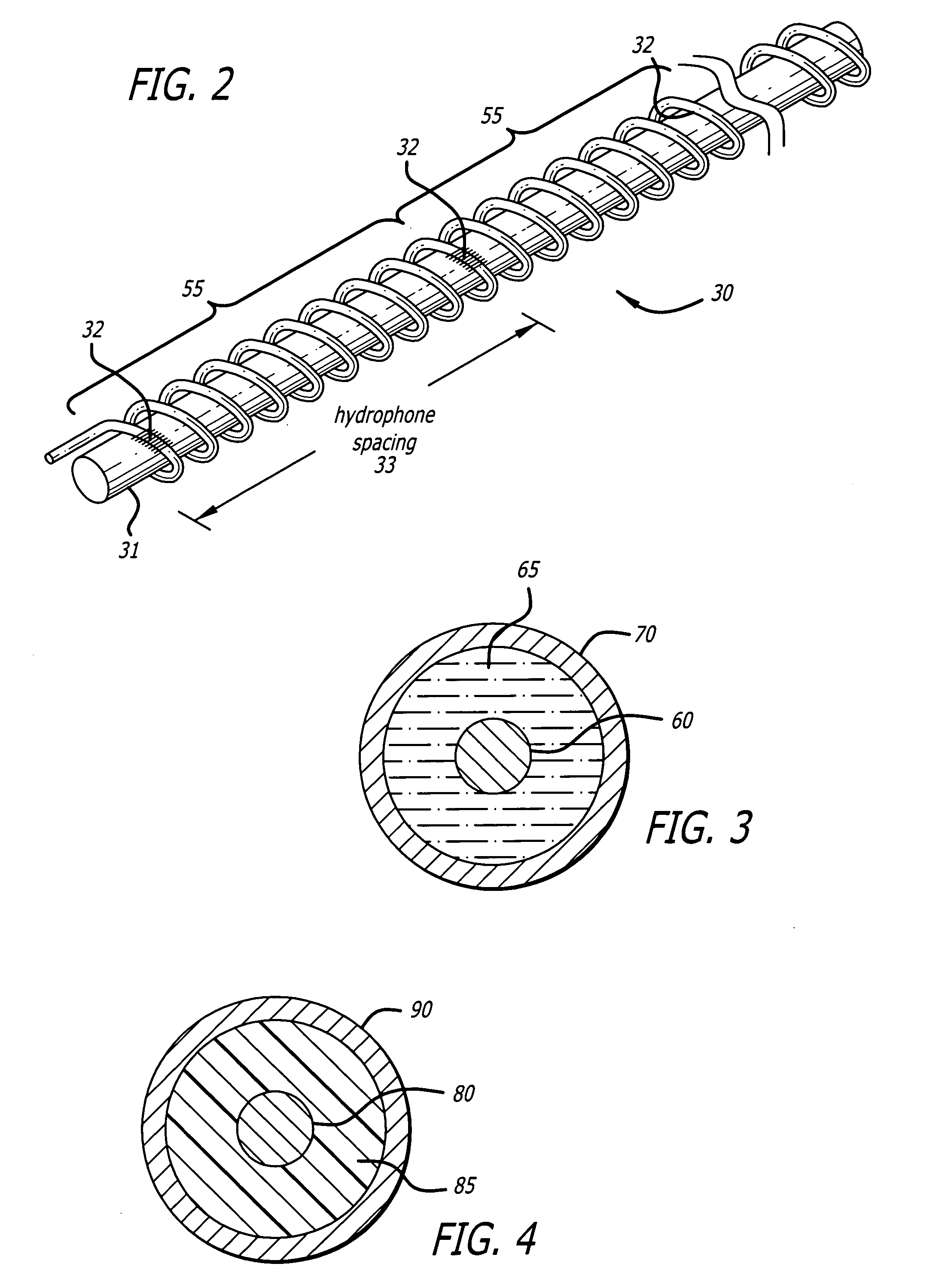
[0041] Referring now to the exemplary drawings, which illustrate, by way of example only, embodiments of the present invention, the present invention is generally embodied in a structure and method for forming that structure that includes a relatively flexible core through which extends an optical fiber. A series of reinforcing and protection layers are further would around the core, one layer of which includes windings of an optical fiber in which are formed one or more gratings, such as long period or Bragg gratings. The entire structure may further be surrounded by an outer jacket. In some embodiments, the resulting cable-line structure may be extended through a protective cylinder formed from a material such as glass, metal, polymer or other material as needed to provide additional protection to the sensor of the present invention depending upon the environment in which the sensor is to be deployed.

[0042]FIG. 1 is an overall view of one embodiment of a solid fiber optic hydroph...


PUM


Abstract

An array of fiber optic hydrophones or geophones is formed by winding of optical fiber around a continuous, yet flexible cylindrical core. The cylindrical core contains an elastomer filled with a specified percentage of voided plastic microspheres. The elastomer provides the necessary radial support of the optical fiber, and with the included voided microspheres, provides sufficient radial compliance under acoustic pressure for proper operation of the hydrophone. The cylindrical core can be made in very long sections allowing a plurality of fiber optic hydrophones to be wound onto it using a single optical fiber, with individual hydrophone elements separated by integral reflectors such as Fiber Bragg Gratings (FBSs). The center of the core may include a strength member and a central hollow tube for the passing of additional optical fibers. The aforementioned hydrophone array is then packaged within a protective outer coating or coatings as required for the specified application.

Description

CROSS-REFERENCE TO RELATED APPLICATION [0001] This application claims priority to U.S. Provisional Application Ser. No. 60 / 416,007, filed Oct. 4, 2002, U.S. Provisional Application Ser. No. 60 / 463,295, filed Apr. 16, 2003, and U.S. Provisional Application Ser. No. 60 / 465,150, filed Apr. 24, 2003, the entirety of which are expressly incorporated herein by reference.BACKGROUND OF THE INVENTION [0002] 1. Field of the Invention [0003] The present invention relates generally to an improved design and construction technique for fiber optic hydrophones and hydrophone arrays. More specifically, the present invention comprises a fiber optic hydrophone that has a continuous solid, yet compliant, elastomer core. In some embodiments, plastic microspheres have been added to the elastomer core to provide increased acoustic compliance. [0004] 2. Description of Related Art [0005] There are many occasions when it is necessary to detect acoustic signals in an underwater environment. For example, geol...

Claims


Application Information

Patent Timeline
IPC IPC(8): G02B6/44G01H9/00G01V1/20G01V1/52
CPCG01H9/004G01V1/201G01V1/208G01V1/52G02B6/4429
Inventor GOLDNER, ERIC L.BRIGGS, WILLIAM
Owner SABEUS PHOTONICS
Learn More