
Apparatus and method for aggregating and switching traffic in subscriber network

a subscriber network and subscriber technology, applied in data switching networks, high-level techniques, multiplex communication, etc., can solve the problems of unsuitable for efficiently processing subscriber traffic, and unsuitable for aggregating subscriber traffic. , to achieve the effect of efficient aggregation, switching and broadcasting subscriber traffi

Inactive Publication Date: 2006-06-08
ELECTRONICS & TELECOMM RES INST
View PDF2 Cites 11 Cited by
  • Summary
  • Abstract
  • Description
  • Claims
  • Application Information

AI Technical Summary

Benefits of technology

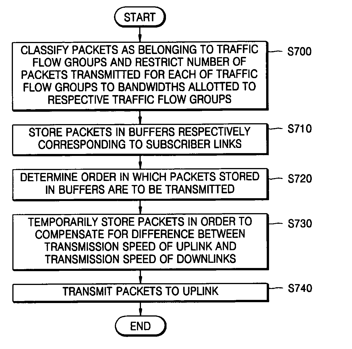
[0016] The present invention provides an apparatus for aggregating and switching traffic in a subscriber network which can enhance buffering efficiency in a broadband subscriber network where upstream traffic and downstream traffic are asymmetric and which can efficiently aggregate, switch, and broadcast subscriber traffic to a plurality of subscribers in the broadband subscriber network by using a single device even when a transmission speed of an uplink is different from a transmission speed of a downlink.
[0017] The present invention also provides a method of aggregating and switching traffic in a subscriber network in which buffering efficiency can be enhanced in a broadband subscriber network where upstream traffic and downstream traffic are asymmetric, and subscriber traffic can be efficiently aggregated, switched, and broadcast to a plurality of subscribers in the broadband subscriber network by using a single device even when a transmission speed of an uplink is different from a transmission speed of a downlink.
[0021] According to another aspect of the present invention, there is provided a method of processing inter-subscriber traffic performed by an apparatus for aggregating and switching traffic in a subscriber network. The method includes: receiving a plurality of packets from a plurality of downlinks, which are subscriber links, and storing the packets with respect to each subscriber link; transmitting the packets to an uplinks through scheduling with respect to each subscriber link; determining whether each of the packets is destined for any of the subscriber links based on header information of the transmitted packets; broadcasting the packets to the subscriber links via a broadcast bus connected to the respective subscriber links if each of the packets is destined for any of the subscriber links; and allowing the subscriber links to determine whether to transmit the packets that they receive.
[0022] Accordingly, it is possible to efficiently aggregate, switch, and broadcast subscriber traffic in a broadband subscriber network where upstream traffic and downstream traffic are asymmetric.

Problems solved by technology

However, conventional Ethernet switches have been designed to serve a LAN and thus may not be suitable for processing subscriber traffic.
Subscriber traffic has a non-uniform distribution of destinations.
In other words, conventional Ethernet switches are designed to be suitable for a LAN with uniform and symmetric user traffic and thus may not be suitable for efficiently processing traffic in a subscriber network with asymmetric traffic.
As a number of ports in a conventional Ethernet switch having a shared buffer or shared bus architecture increases, an operating speed of a shared buffer or shared bus must increase accordingly, and this requirement makes it almost impossible to accommodate a considerable number of subscribers using a single device as specified by Nick McKeown [The iSLIP Scheduling Algorithm for Input-Queued Switches, IEEE / ACM Transactions on Networking, Vol. 7, pp.
Accordingly, in a case where multicast traffic having a high priority level, such as broadcast traffic, occupies most of the bandwidths available to a conventional Ethernet switch, the amount of resources that other traffic having lower priority levels can use may decrease considerably, and thus, the quality of data transmission may considerably deteriorate.

Method used


Image

  • Apparatus and method for aggregating and switching traffic in subscriber network
  • Apparatus and method for aggregating and switching traffic in subscriber network
  • Apparatus and method for aggregating and switching traffic in subscriber network

Examples


Embodiment Construction

[0032] The present invention will now be described more fully with reference to the accompanying drawings in which exemplary embodiments of the invention are shown.

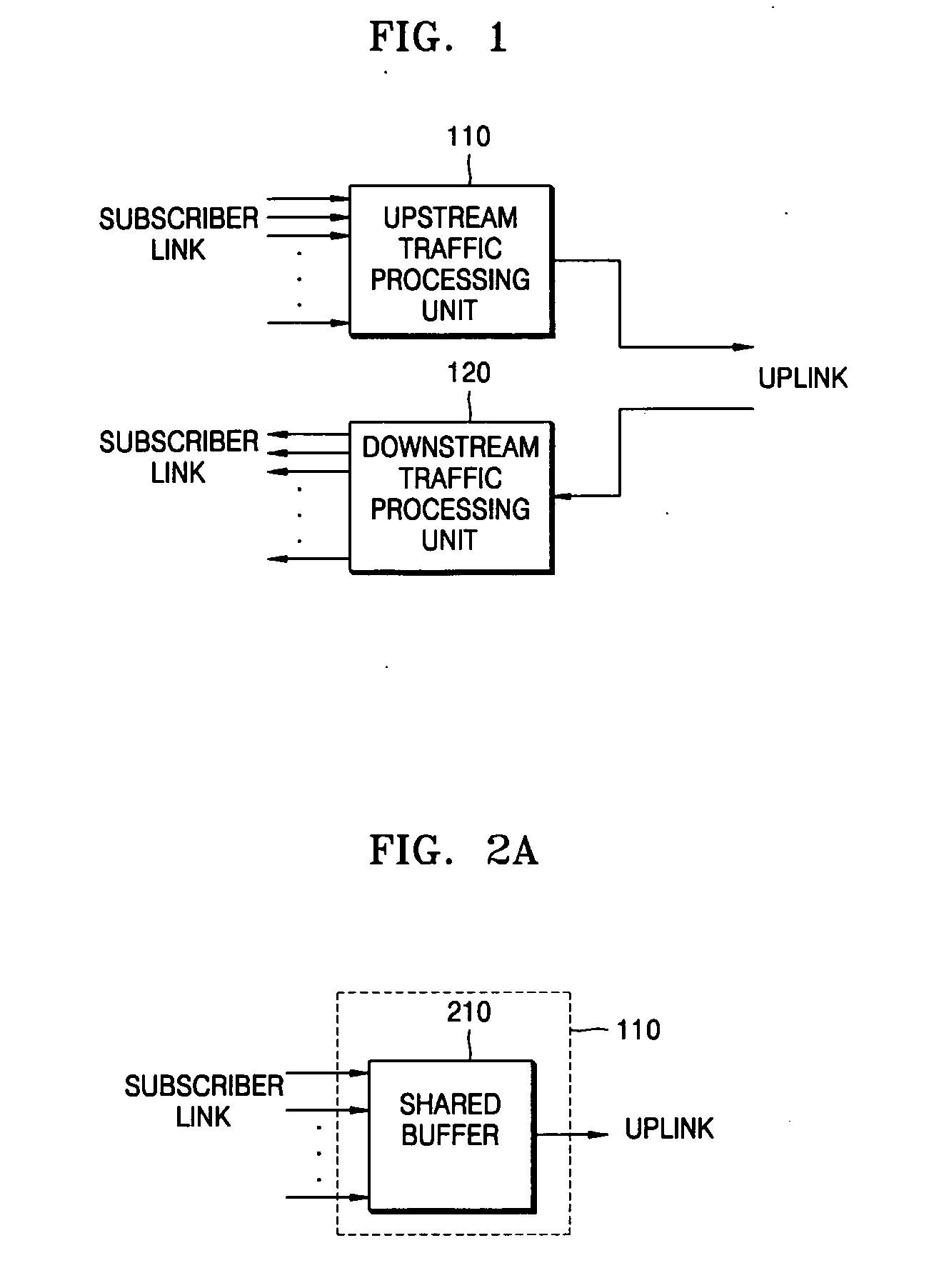
[0033]FIG. 1 is a block diagram of an apparatus for aggregating and switching traffic in a subscriber network according to an exemplary embodiment of the present invention. Referring to FIG. 1, the apparatus includes an upstream traffic processing unit 110 and a downstream traffic processing unit 120. The apparatus classifies subscriber traffic into upstream traffic or downstream traffic. In the present embodiment, it is assumed that there is nearly no inter-subscriber traffic.

[0034] A process of processing upstream traffic will now be described in detail.

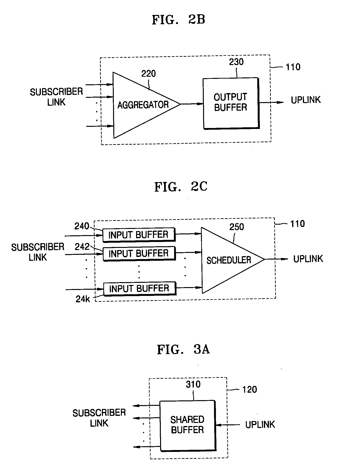
[0035] The apparatus of FIG. 1 processes upstream traffic and downstream traffic separately. In other words, the apparatus processes upstream traffic using the upstream traffic processing unit 110 and processes downstream traffic using the downstream traffic processin...


PUM


Abstract

An apparatus for aggregating and switching traffic in a broadband subscriber network and methods of processing upstream and downstream traffic are provided. The apparatus includes: an upstream traffic processing unit which stores a plurality of packets received from a plurality of downlinks with respect to each subscriber link, and transmits the packets stored with respect to each subscriber link to uplinks through scheduling; and a downstream traffic processing unit which broadcasts a packet received from the uplinks to the subscriber links via a broadcast bus connected to the respective subscriber links and determines with respect to each subscriber link whether to transmit the packet to subscriber links. It is possible to efficiently aggregate, switch, and broadcast subscriber traffic in a broadband subscriber network in which upstream traffic and downstream traffic are asymmetric.

Description

CROSS-REFERENCE TO RELATED PATENT APPLICATION [0001] This application claims the benefit of Korean Patent Application Nos. 10-2004-0102509, filed on Dec. 7, 2004, and 10-2005-0033526, filed on Apr. 22, 2005, in the Korean Intellectual Property Office, the disclosures of which are incorporated herein in their entirety by reference. BACKGROUND OF THE INVENTION [0002] 1. Field of the Invention [0003] The present invention relates to an apparatus and method for aggregating and switching traffic in a subscriber network, and more particularly, to an apparatus and method for aggregating and switching traffic in a subscriber network, which can efficiently aggregate and switch subscriber traffic with various bandwidths in a broadband subscriber network where upstream traffic and downstream traffic are asymmetric. [0004] 2. Description of the Related Art [0005] Major increases in Internet data transmission speeds have opened the way for the commercialization of various multimedia services, su...

Claims


Application Information

Patent Timeline
IPC IPC(8): H04L12/56
CPCH04L12/2854H04L47/10H04L47/15H04L47/20H04L47/22H04L47/2416H04L47/2441H04L47/283H04L47/41Y02B60/33Y02D30/50
Inventor LEE, HYOUNG IILEE, JEONG HEELEE, BHUM CHEOL
Owner ELECTRONICS & TELECOMM RES INST
Learn More