Surface light source device, display device having the same, and method of controlling the display device

Inactive Publication Date: 2006-06-08
SAMSUNG ELECTRONICS CO LTD +1
View PDF7 Cites 38 Cited by
  • Summary
  • Abstract
  • Description
  • Claims
  • Application Information

AI Technical Summary

Benefits of technology

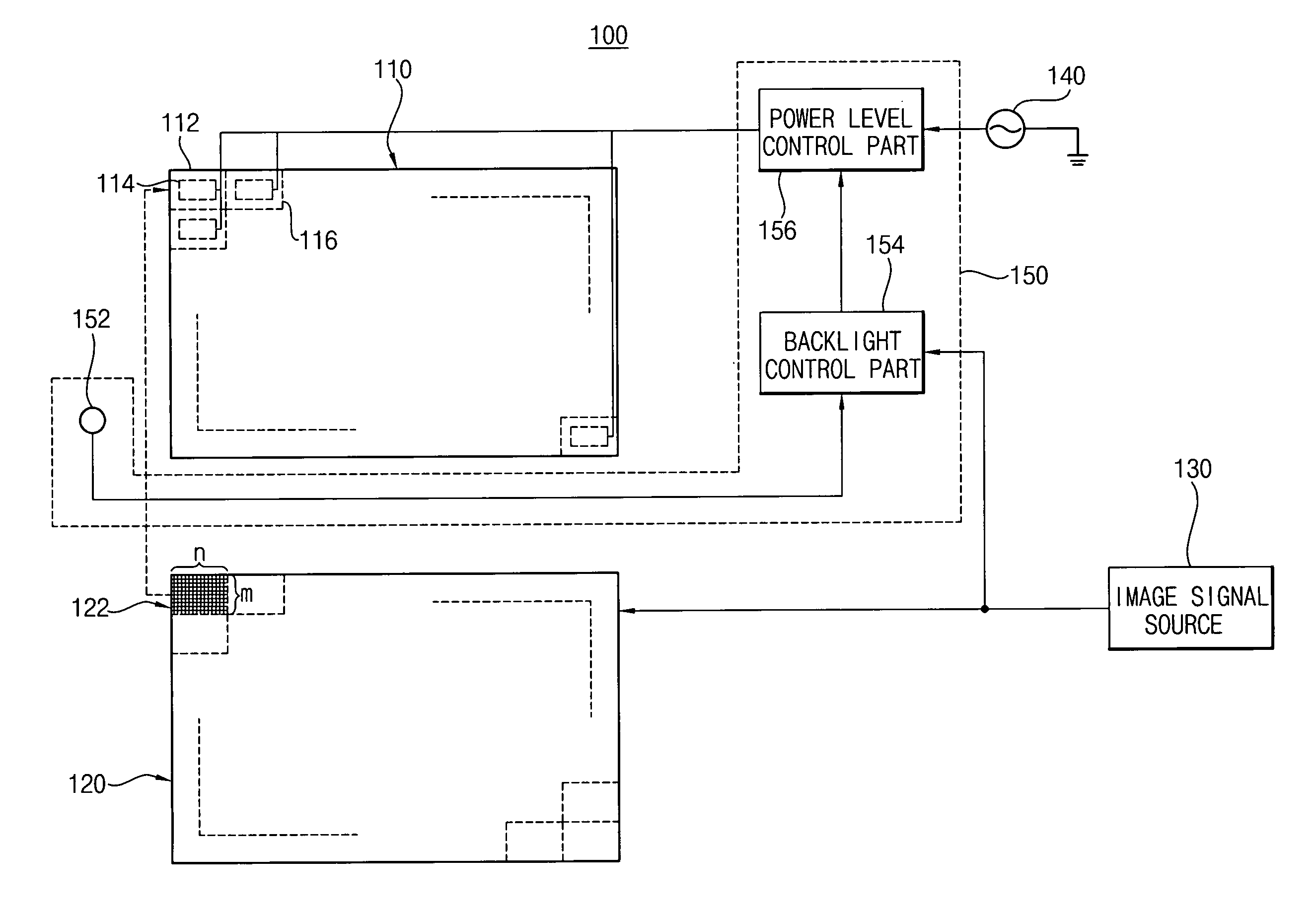
[0014] The present invention also provides a display device including the surface light source device, which is capable of gaining high contrast and efficiently reducing power consumption by partially controlling brightness of a light source according to properties of images displayed by a display panel of the display device.
[0020] In yet other exemplary embodiments of the present invention, a method of reducing power consumption in a display apparatus includes segmenting a surface light source unit into discrete sections, detecting image signals applied to a display panel, independently controlling the sections of the surface light source unit at least partially in response to the image signals, and applying light from the sections of the surface light source unit to the display panel.
[0022] Further, when images displayed on the display apparatus, having the exemplary embodiments of the surface light source, are partially dark or bright, relatively high contrasts and relatively low power consumption are obtained by controlling brightness of the light source to be partially dark or bright according to the properties of the images.

Problems solved by technology

Thus, when a screen is partially dark or bright, obtaining a high contrast is difficult.
Further, when a dark scene is displayed by the controlling of a light source device, power consumption by a light source device may be lowered.
However, when a partially bright scene is displayed, brightness of a light source device is totally increased, so that power consumption is still relatively high.

Method used


Image

  • Surface light source device, display device having the same, and method of controlling the display device
  • Surface light source device, display device having the same, and method of controlling the display device
  • Surface light source device, display device having the same, and method of controlling the display device

Examples


embodiment 1

of a Surface Light Source Device

[0126]FIG. 15 is a perspective view illustrating an exemplary embodiment of a surface light source device according to the present invention. FIG. 16 is a cross-sectional view illustrating the exemplary surface light source device in FIG. 15. FIG. 17 is another cross-sectional view illustrating the exemplary surface light source device in FIG. 15.

[0127] Referring to FIGS. 15 to 17, a surface light source device 350 includes a flat discharge tube 351, a first electromotive force generating part 360, and a second electromotive force generating part 370. The surface light source device 350 emits light of which luminance is adjusted according to properties of image signals. The first and second electromotive force generating parts 360 and 370 cover first and second end portions of the flat discharge tube 351, respectively.

[0128] The flat discharge tube 351 includes two substrates facing each other, an upper electrode and a lower electrode dividing or de...

embodiment 2

of a Surface Light Source Device

[0134]FIG. 18 is a cross-sectional view illustrating another exemplary embodiment of a surface light source device according to the present invention.

[0135] Referring to FIG. 18, a surface light source device 450 includes a flat discharge tube 351, a first electromotive force generating part 360, a second electromotive force generating part 370, and a plurality of cores 457, such as ferrite cores. The plurality of cores 457 is disposed on a backside of the flat discharge tube 351. Each of the cores 457 is small and single wired. A coil may be wound around the cores 457. The surface light source device 450 emits light, when the surface light source device 450 receives electric powers controlled by each property of image signals. The same reference numerals are used to refer to the same or like parts as those described in FIGS. 15 to 17, and any further explanations will be omitted.

Embodiment 3 of a Surface Light Source Device

[0136]FIG. 19 is a cross...

embodiment 4

of a Surface Light Source Device

[0138]FIG. 20 is a cross-sectional view illustrating still another exemplary embodiment of a surface light source device according to the present invention. FIG. 21 is a cross-sectional view illustrating the exemplary surface light source device in FIG. 20.

[0139] Referring to FIGS. 20 and 21, a surface light source device 650 includes a flat discharge tube 651, a first electromotive force generating part 660, and a second electromotive force generating part 670. The surface light source device 650 emits light when the surface light source device 650 receives electric power controlled by each property of image signals. The first electromotive force generating part 660 covers a first edge portion area of the flat discharge tube 651. The second electromotive force generating part 670 covers a second edge portion of the flat discharge tube 651. The first edge portion is opposite to the second edge portion.

[0140] The flat discharge tube 651 includes an u...


PUM


Abstract

A surface light source includes a discharge tube, a power source, and a surface light source control part. The discharge tube includes a plurality of lighting areas. Each lighting area has a discharge electrode part. The power source applies electric power to the discharge electrode parts. The surface light source control part separately controls brightness of each lighting area by separately controlling electric power levels applied to the discharge electrode part of each lighting area, respectively. Therefore, relatively high contrasts and relatively low power consumption are obtained.

Description

[0001] This application claims priority to Korean Patent Application No. 2004-94280, filed on Nov. 17, 2004, and Korean Patent Application No. 2005-74857 filed on Aug. 16, 2005 and all the benefits accruing therefrom under 35 U.S.C. §119, and the contents of which in their entireties are herein incorporated by reference. BACKGROUND OF THE INVENTION [0002] 1. Field of the Invention [0003] The present invention relates to a surface light source device, a display device having the same, and a method of controlling the display device. More particularly, the present invention relates to a surface light source device having a brightness adjusting function, a display device having the same, and a method of controlling the display device. [0004] 2. Description of the Related Art [0005] In general, a light transmissivity of a liquid crystal is altered corresponding to an electric field applied thereto. A liquid crystal display (“LCD”) device displays an image by controlling the liquid crysta...

Claims


Application Information

Patent Timeline
IPC IPC(8): F21V23/04
CPCG02F1/133603G02F1/133604G02F1/133611G02F2001/133612G02F2201/58G09G3/3426G09G3/3611G09G2310/024G09G2320/0646G09G2360/144G09G2360/16G02F1/133612
Inventor CHOO, DAE-HOCHOI, DAE-KYU
Owner SAMSUNG ELECTRONICS CO LTD
Why Eureka
Try Eureka