
System, apparatus and method for detection of electrical faults

a technology of electrical faults and systems, applied in the field of system, apparatus and method for detection of electrical faults, can solve the problems of faulty wiring, 700 deaths and $700 million in property losses, and the common failure of the power supply to the load in the facility, and achieve the effect of improving electrical fire protection and being cheaper to implemen

Active Publication Date: 2006-06-08
ISRA JUK ELECTRONICS
View PDF22 Cites 117 Cited by
  • Summary
  • Abstract
  • Description
  • Claims
  • Application Information

AI Technical Summary

Benefits of technology

[0025] The said communication may include more than one communication means at a time. For example, using RF together with powerline messaging. This will achieve higher robustness of communication together with range expansion. Furthermore, communication may use two different methods on the same media at the same time such as digital-modem and analog-modulation over the powerline.
[0030] In addition, the implementation of an apparatus that displays the values measured and / or computed and allows a person to analyze them is also applicable. Such an apparatus can be configured without any communication media at all and can therefore be very cheap and easy to implement and install. Such an apparatus—with or without communication means may be used to measure the percentage of the mains voltage-drop—from the mains-supply to the location where it is measured—during normal use. It should be stressed out that such systems currently available in the market enable measurement of such voltage drop only with a controlled load connected to the mains. The present invention is capable of measuring the voltage drop on the power grid during the normal mode of operation. In addition, the present invention may be used instead of infra-red detection of glowing-connections in the mains wiring. Infra-Red thermal-check equipment is expensive, can only detect problems in places that can be photographed and on top of this it requires the problem to happen when the Infra-Red equipment photographs the suspected area. Consequently, if a problem develops in a place where photography is not possible, or when the mains wiring is cannot be thermally photographed—then the faulty condition will not be detected by Infra-Red thermal-check. The present invention will use equipment that can be installed as part of the wiring system for long periods of time—even as an integral part of the wiring system, and automatically detect glowing-connected conditions by analyzing the voltage drops over the powerline grid.
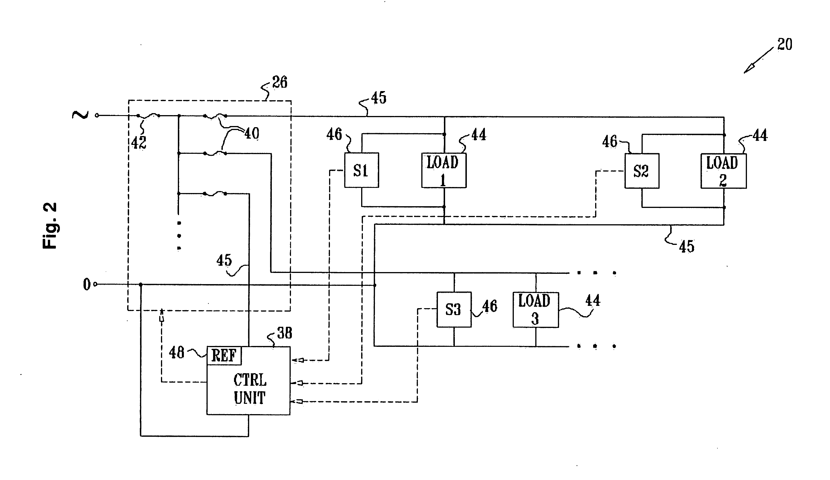
[0035] In an embodiment of the invention, each (or at least some) of the local sensing devices may include a circuit breaker, which is controllable to cut off the power to the respective load when the processor detects the fault. Alternatively, a relay that will generate a ground-fault may be used. This can be useful in facilities that have a ground-fault circuit-interrupter being part of them. An intentionally-generated such a ground-fault will cause the ground-fault circuit-interrupter to trip—and de-energize a larger part of the facility or even the whole facility. Such mechanism of electrical power disconnection in case of a fault-detection may be cheaper to implement and may provide better electrical-fire protection than disconnection of the faulty-load itself.

Problems solved by technology

Despite the fact that modern buildings and other facilities are equipped with modern electrical-fire prevention devices, improper power supply to loads in a facility are common and remain a severe hazard.
According to the U.S. Fire Administration, for example, home electrical problems have recently accounted for 90,000 fires each year, causing over 700 deaths and $700 million in property losses.
Such fires result from faulty wiring, from faults in appliances connected to the wiring, faults in the connections between the wiring itself or from any other part of the electrical system that conducts electrical current to the electrical loads.
The electrical disturbance can be intermittent or fixed, thus leading to a time-to-time disturbance in the required operation of the electrical loads or preventing them from working at all.
Many electrical fires are a direct result of an electrical fault, in which the temperature of an electrical conductor significantly increases.
However, these devices are designed to treat all the resistance or impedance of the circuit as one equivalent resistor, and therefore have no indication of the amount of energy dissipation over each of the conductors, resistors, capacitors, coils, and other parts comprising the circuit.
In addition, aging of the wiring within a facility creates “parasitic” resistors, which consume additional power.
Existing protection devices lack the ability to measure power ratio between a desired load and a parasitic one.
Such cases can also be found in faulty wiring problems that create a short-circuit, whereas the series-connection with the parasitic resistance limits the current through the shortened circuit to be below the tripping level of the fuse or the circuit-breakers being used.
In other cases, the temperature increase over the parasitic resistance is itself a cause for a fire.
This leads to a significant increase in the temperature of the parasitic loads of the electrical system and may ignite a fire.
As a result, current passing through the protection device causes dissipation of energy across the protection device itself.
This may lead to heating of that protection device and additional undesired phenomena such as corrosion, carbonization of conductors and mechanical deformation of the different parts comprising the protective device itself.
Hence, the protection device's capability to detect an electrical-current fault is severely affected.
However, these checks require special equipment, which does not operate constantly as part of the inspected facility.
Therefore, these appliances can only detect a problem that occurs when such a specific test equipment is set to perform the tests.
One of the fundamental drawbacks common to all above-mentioned prior art devices is the fact that they all operate post factum.
In many cases this is usually too late to prevent the risk of fire from materializing.
A further drawback of prior art device is that they are all current-oriented devices.
The problem with protection systems based on measuring current is that parasitic resistance in the electrical circuit acts as a current limiter which prevents the protection devices from tripping—even when the original load becomes a short circuit.
The terminology used—of detecting short-circuits only—emphasizes the limited capabilities of such systems.
It should be noted in particular that none of the existing methodologies propose a system for an early detection of electrical fault in an electrical system by monitoring voltage levels in parallel to loads within a facility.

Method used


Image

  • System, apparatus and method for detection of electrical faults
  • System, apparatus and method for detection of electrical faults
  • System, apparatus and method for detection of electrical faults

Examples


Embodiment Construction

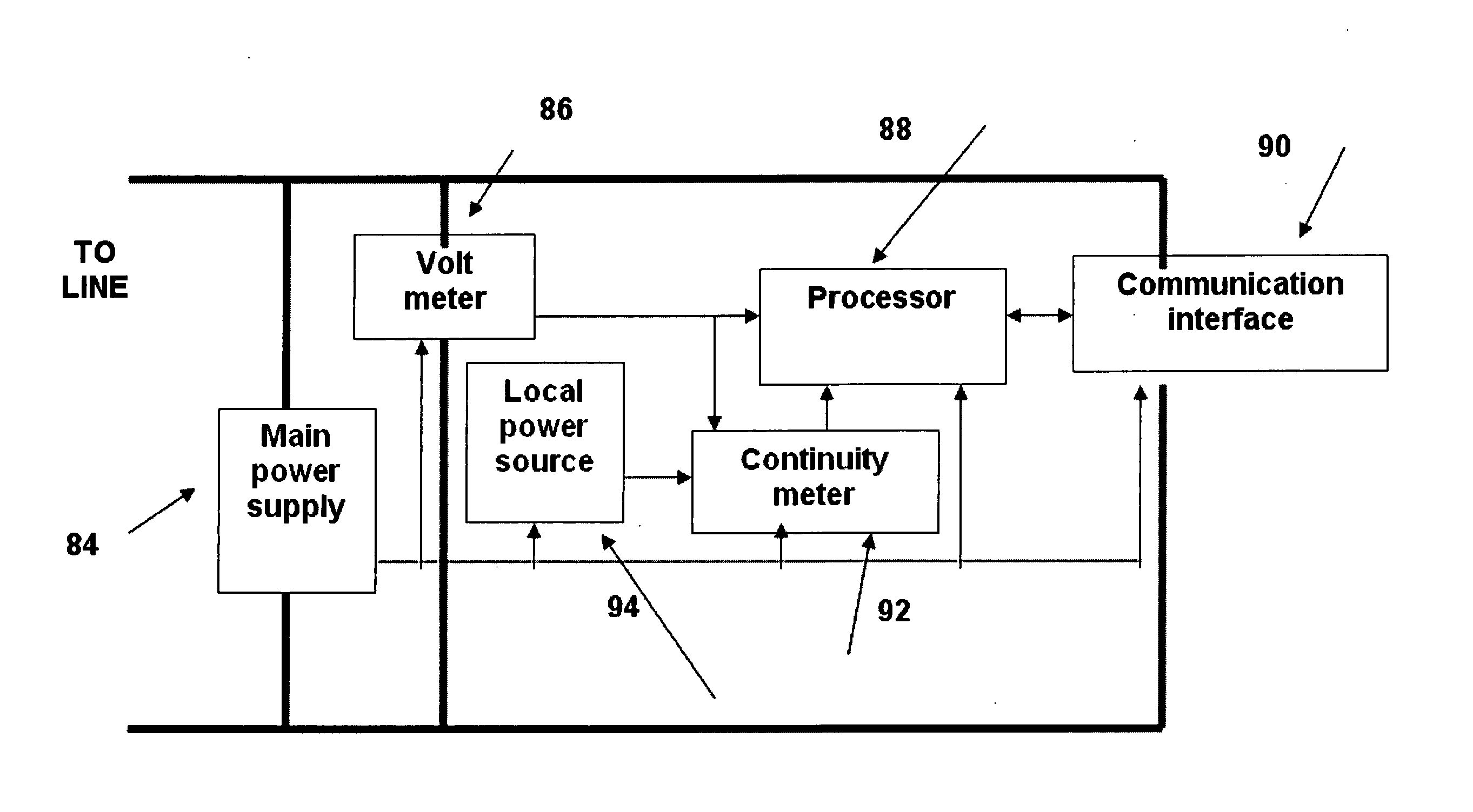
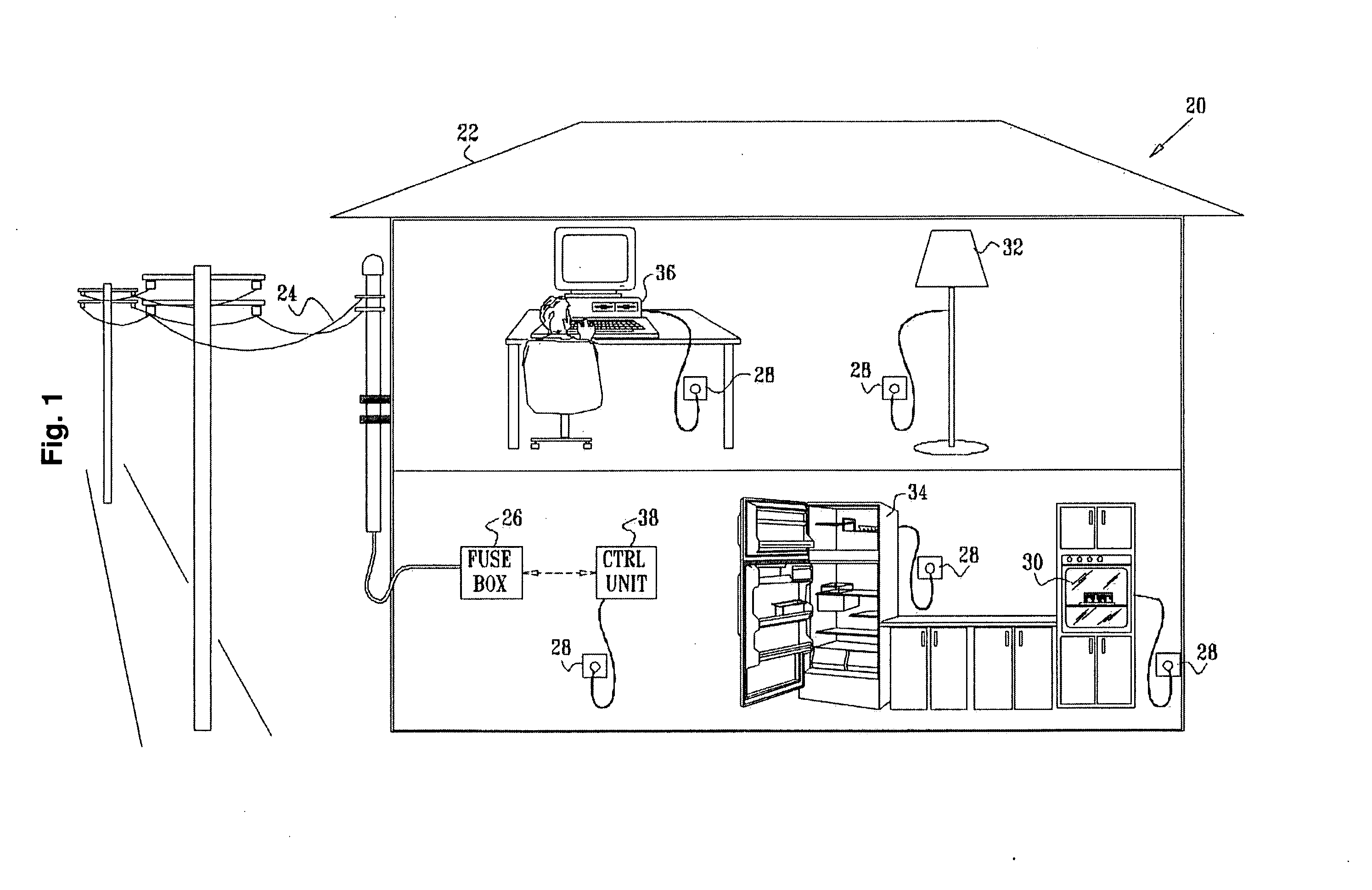
[0055] The proposed system according to the present invention provides early, manual and / or automatic detection of electrical faults in wiring systems and / or in the loads connected to the system. The system can be implemented as a single apparatus, for performing local tests, or may be further implemented as a system and provide detection of electric faults on a plurality of wiring systems and connected loads. An early detection spares the need to immediately disconnect the system from the main power supply. The system is provided to monitor local voltage levels across electrical loads and continuity measurements since electrical-power was continually supplied to one or more points in the electrical system of a facility, such as a home, business, vehicle, aircraft or ship. By measuring and tracking changes in the local voltage and continuity measurements regarding the presence of electrical-power, the system is able to detect changes and events that may be indicative of faults in th...


PUM


Abstract

System for monitoring an electrical system of a facility includes one or more local sensing devices, each of which is adapted to be connected to the electrical system of the facility in proximity to a respective load that receives power from the electrical system so as to make local measurements of a voltage across the load continuity measurements of electrical-power presence at one or more points in the electrical system of said facility. A processing unit is adapted to receive and compare the local measurements to reference measurements of the voltage supplied to the facility, in order to detect a fault in the electrical system.

Description

[0001] The application is a continuation in part, claiming priority from PCT application no. PCT / IL04 / 000612 filed on Jul. 8, 2004 having a priority date of Jul. 9, 2003. The present invention relates to the field of electrical safety. More particularly, the invention relates to systems and methods providing an early, manual or automatic detection of electrical faults in wiring systems and connected appliances.BACKGROUND OF THE INVENTION [0002] Nearly all facilities that use electricity are equipped with a system containing fuses and / or circuit breakers, thus applied to cut off electrical supply when an electrical fault occurs. These devices operate by sensing excess current or other current-related phenomena, which typically occurs due to a short circuit, connection / disconnection of loads, short-term wiring disconnections or other electrical faults. (For example, arc-fault circuit interrupters detect current changes that are typical of arc-faults, while ground-fault circuit interru...

Claims


Application Information

Patent Timeline
IPC IPC(8): G01R31/08H01HH02J7/00
CPCG01R19/2513G01R31/025G01R31/086G01R31/12H02J7/0042H02J2001/006H02H7/26H02H7/263H02H3/042H02J1/122G01R31/52Y04S10/52G01R31/54H02H3/50
Inventor SELA, ISAACBENDER, ELIYAHU-YOSEF
Owner ISRA JUK ELECTRONICS
Learn More