
Stereo widening network for two loudspeakers

a stereo widening network and loudspeaker technology, applied in the field of audio processing, can solve the problems of insufficient spatial effect, insufficient area between them, and small performance reduction, and achieve the effect of computationally extremely efficient and advantageous sound quality

Active Publication Date: 2006-06-01
WSOU INVESTMENTS LLC
View PDF14 Cites 33 Cited by
  • Summary
  • Abstract
  • Description
  • Claims
  • Application Information

AI Technical Summary

Benefits of technology

[0016] This invention describes a digital signal processing algorithm that can extend the sound stage beyond the angle spanned by two loudspeakers. Since the strength of the spatial effect is adjustable, any compromise between spatial effect, loudness and sound quality under the constraint of the limited acoustic output available from the two small loudspeakers can be achieved.
[0017] The stereo widening network is used to give a listener the impression that the sound comes from positions outside the angle spanned by two loudspeakers. Therefore the invention improves enormously the output of two closely spaced loudspeakers, such as those locating on different sides (left, right, above, below) of the screen, as in mobile phones or another type of portable devices. The loudspeakers can naturally be a separate component that can be attached in a known manner to an electronic device.
[0018] According to the solution the sound quality is optimal at the centre of the sound stage. This improves the solutions of related art enormously, because previously the centre has received no attention. In addition, the spatial effect is adjustable on a continuous scale.
[0020] With an optional pre-processing module there is an alternative way to adjust the strength of the spatial effect, hence providing advantage to the sound quality.
[0021] The solution according to the invention is computationally extremely efficient, which has a great benefit not only with portable devices but also with other electronic devices.

Problems solved by technology

In this publication, the gain of the off-diagonal elements of the symmetric 2-by-2 filter matrix is reduced, thereby increasing the size of the sweet spot at the expense of a modest decrease in performance.
It is easily appreciated that when two loudspeakers are close together, the area between them is not wide enough for the spatial effect resulting from moving the sources around inside the area.
However, not much attention has been paid to it in the context of spatial enhancement systems.
It can be seen, that the solutions of related art may not fulfil the requirements of all the current electronic devices.

Method used


Image

  • Stereo widening network for two loudspeakers
  • Stereo widening network for two loudspeakers
  • Stereo widening network for two loudspeakers

Examples


Embodiment Construction

[0027] Although specific terms are used in the following description for the sake of clarity, these terms are intended to refer only to the particular structure of the subject-matter selected for illustration in the drawings and are not intended to define or limit the scope of the invention.

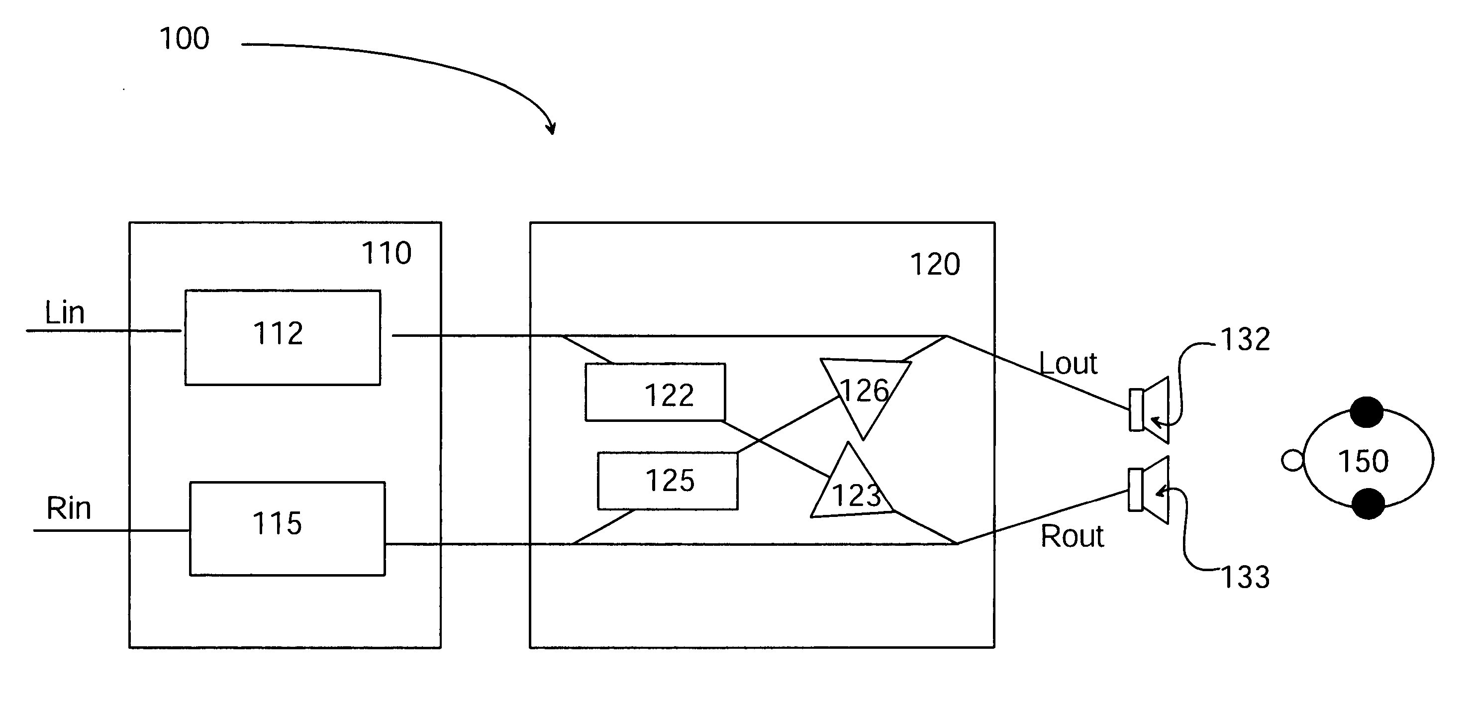
[0028]FIG. 1 illustrates a possible configuration of a stereo widening network 100. In this example the network comprises left (Lin) and right (Rin) inputs and corresponding outputs (Lout, Rout). Two audio channels are taken in and processed in the network 100. The two main parts of the stereo widening network 100 are an equalizer 110 and a cross-talk network 120. The function of the equalizer 110 is to filter each of the audio channels (Lin, Rin), e.g. by two IIR comb filters (Infinite Impulse Response) 112, 115. The function may be similar for each of the channels (Lin, Rin): EQ⁡(z)=11-gz-N,

[0029] The function of the cross-talk network 120 is to mix the direct channel (from the equalizer) wit...


PUM


Abstract

The invention relates to a method, a system, a module, an electronic device and to a computer program product for widening a two-channel input. Two audio channels are input and filtered by equalizing said channels. The filtered channels are mixed with their opposite channels in a cross-talk network and output from loudspeakers and by this providing a spatial impression for audio.

Description

FIELD OF THE INVENTION [0001] This invention relates generally to audio processing and particularly to such an audio processing, where two-channel input is widened when using two loudspeakers. BACKGROUND OF THE INVENTION [0002] Spatial sound is possible to create by a surround system that comprises different loudspeakers for different audio channels. In a standard setup of a stereo system of two loudspeakers, said loudspeakers span 60 degrees. For giving the impression that sound sources move around inside the area between the two loudspeakers, amplitude panning can be used. Such sound sources, whose positions correspond to positions away from the loudspeakers are usually referred to as “virtual sources” or “phantom images”. In other words, a virtual sound source is localized by the listener, but is not produced by a loudspeaker at the location. [0003] Patent publication U.S. Pat. No. 3,236,949 presents a cross-talk cancellation network, which was the first description of how to mak...

Claims


Application Information

Patent Timeline
Patent Type & Authority Applications(United States)
IPC IPC(8): H04R5/00H03G5/00
CPCH04R5/04H04S1/002H04S1/00
Inventor KIRKEBY, OLE
Owner WSOU INVESTMENTS LLC
Learn More