Back-lighting unit and liquid crystal display using the same

Inactive Publication Date: 2006-06-01
NEC LCD TECH CORP
View PDF9 Cites 69 Cited by
  • Summary
  • Abstract
  • Description
  • Claims
  • Application Information

AI Technical Summary

Benefits of technology

[0013] Accordingly, an exemplary feature of the invention is to provide a back-lighting unit excellent in color reproduction of emitting light therefrom, adequate for heightening brightness of the emitting light, and capable of suppressing brightness non-uniformity of the emitting light.
[0035] Consequently, according to the back-lighting unit of the invention, as a first effect, a high-brightness back-light with a relatively narrow bezel area can be obtained, the back-light being excellent in surface uniformity of luminance. For example, a back-lighting unit can be obtained in which a brightness difference is small between edge parts and a central part of the first light guide plate, the back-light being excellent in surface uniformity of luminance. In other words, the back-lighting unit can be obtained in which a brightness difference is small between an edge part of the first light guide plate and the other edge part opposite thereto, the back-light being excellent in surface uniformity of luminance.
[0036] One reason for the above is that plural colors are mixed in the second light guide plates arranged at the back surface of the first light guide plate, and light resulting from the color mixing is allowed to respectively enter two opposite edges of the first light guide plate. Another reason is that the LED array substrate is arranged at a position corresponding to a central part of the first light guide plate, and color mixing is caused by allowing light emitted by light emitting diodes arrayed on the LED array substrate to enter the second light guide plates at both sides of the LED array substrate. That is, it is possible to cause color mixing of the emitting light from the LEDs on the LED array substrate in a well-balanced manner to obtain white light and to allow the white light to enter the first light guide plate.
[0037] Furthermore, as a second effect, module strength can be enhanced.
[0038] The reason for the above is that balance of the entire unit is enhanced since the entire unit substantially has a structure which is line-symmetric with respect to a central part thereof.
[0039] Furthermore, according to the liquid crystal display of the invention, it is possible to realize a liquid crystal display with a relatively narrow bezel area. Furthermore, total module strength of a liquid crystal display is enhanced. By using high-brightness and high-power LEDs, it becomes possible to realize a high-brightness full-color multilevel halftone liquid crystal display with a wide color reproduction gamut.

Problems solved by technology

In the back-lighting unit described as above, however, there is the possibility that following problems occur.
A first problem is that there is a limit in heightening brightness of emitting light from the light guide plate 106.
Furthermore, a difference in brightness in emitting light between two opposite edges of the light guide plate 106 tends to be large, that is, brightness non-uniformity tends to occur.
A second problem is that the back-lighting unit is structurally out of proper proportion.

Method used


Image

  • Back-lighting unit and liquid crystal display using the same
  • Back-lighting unit and liquid crystal display using the same
  • Back-lighting unit and liquid crystal display using the same

Examples


Embodiment Construction

[0058] Hereinafter, exemplary embodiments of the invention will be described in detail with reference to the drawings.

[0059] First, a back-lighting unit according to a first exemplary embodiment of the invention will be described in detail with reference to the drawings.

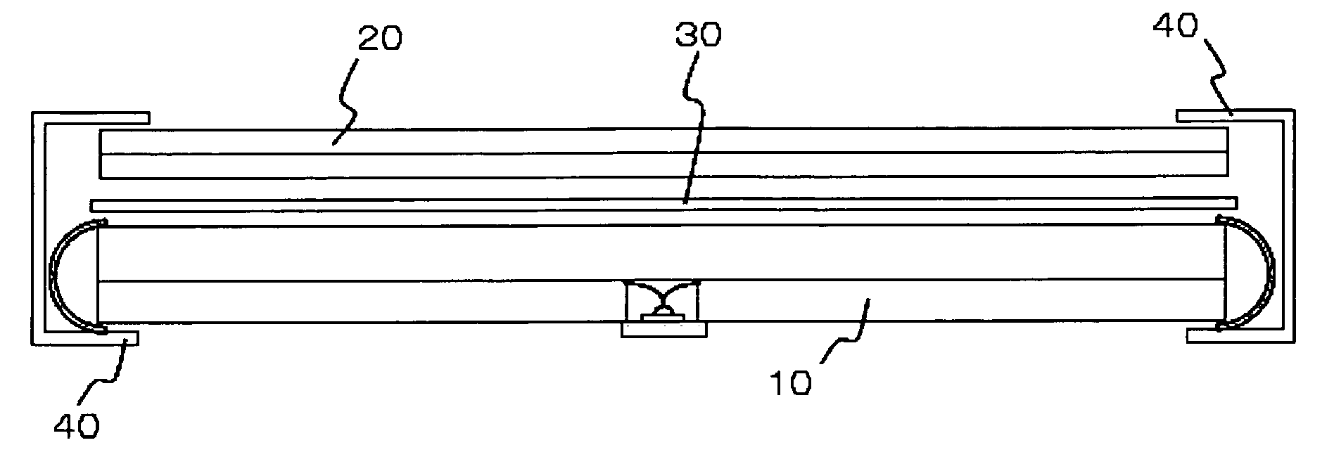
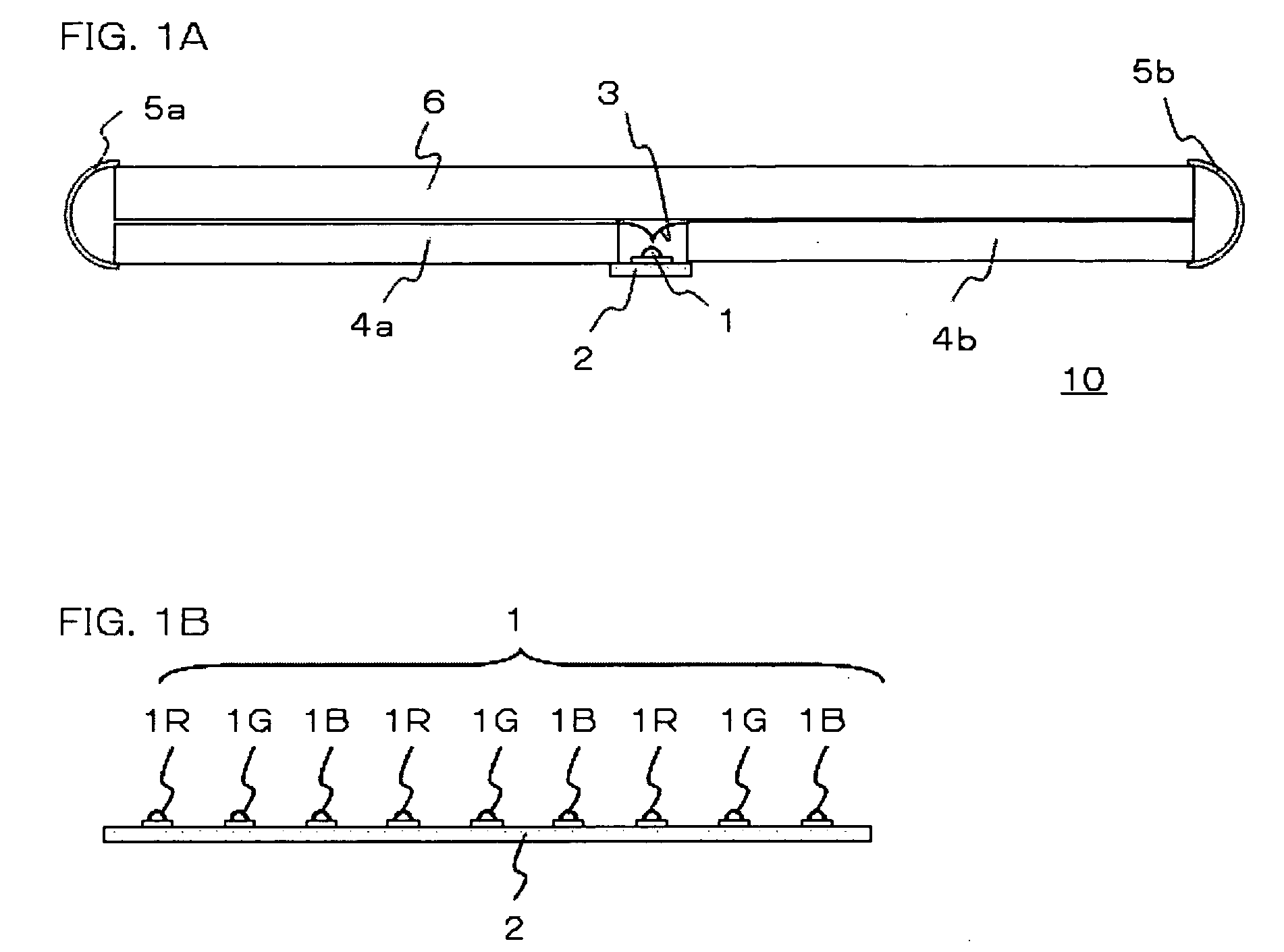
[0060] A back-lighting unit 10 of this embodiment, as shown in FIGS. 1A and 1B, includes: a first light guide plate 6 which radiates out, from one main front surface thereof, light having entered the first light guide plate 6; an LED array substrate 2 arranged at a back surface of the first light guide plate 6 and including three color LEDs 1 (red LEDs, green LEDs and blue LEDs) arrayed thereon; a first optical member 3 which reflects light emitted by the LEDs 1 on the LED array substrate 2; a plurality of second light guide plates 4a and 4b for light color mixing, into each of which color light beams respectively emitted by the red LEDs, green LEDs, and blue LEDs on the LED array substrate 2 enter through one edge...


PUM


Abstract

Light color beams respectively from LEDs formed on an LED array substrate are allowed to enter one edge of second light guide plates for color mixing, which is arranged to either side of the LEDs. In each of the second light guide plates, color mixing of the respective color light beams occurs with increasing distance from this one edge, and thereby white light is obtained. This white light is guided out through the other edge of the second guide light plate, is reflected by a second reflection plate, and then is allowed to enter either of two opposite edges of a first light guide plate. The white light having entered the first light guide plate is radiated out from a front surface thereof.

Description

BACKGROUND OF THE INVENTION [0001] 1. Field of the Invention [0002] The present invention relates to a back-lighting unit, and to a liquid crystal display using the same. In particular, the invention relates to a back-lighting unit using light emitting diodes in plural colors as a light source, and to a liquid crystal display using the same. [0003] 2. Description of the Related Art [0004] For a liquid crystal display, since it is a display device which does not emit light by itself, a front-lighting unit or a back-lighting unit is often used for the purpose of enhancing visibility and brightness of the device. As a light source for a back-lighting unit constituting a back-lighting unit, fluorescent lamps have been mainly used until recently, but it has been proposed to use light emitting diodes (LEDs) having advantages which are a long lifetime and an excellent luminous efficiency. [0005] The back-lighting unit using light emitting diodes as a light source is proposed in “High-effic...

Claims


Application Information

Patent Timeline
IPC IPC(8): F21V7/04F21S2/00F21S8/04F21V8/00F21Y101/02G02F1/13357
CPCG02B6/0031G02B6/0043G02B6/0068G02B6/0076G02B6/0078G02F1/133603G02F1/1335
Inventor IKI, SEIJIMORITA, TOSHIYUKI
Owner NEC LCD TECH CORP
Why Eureka
Try Eureka