
Integral input shaft brake and disconnect apparatus

Inactive Publication Date: 2006-06-01
EATON INTELLIGENT POWER LIMITED
View PDF12 Cites 4 Cited by
  • Summary
  • Abstract
  • Description
  • Claims
  • Application Information

AI Technical Summary

Benefits of technology

[0012] According to other aspects of the present invention, the combination may also include a return spring that operatively engages the brake piston to bias the brake piston against applying a braking force to the rotor and also causing the fluid to flow from the second fluid cavity to the first fluid cavity.
[0016] The method may alternatively be described as comprising the first cavity being pressurized to a first level A at which the disconnect piston is shifted. The pressure in the first cavity may be increased to a second level B wherein the pressurized fluid is provided to the second cavity to shift the brake piston and apply a braking force to the rotor. The braking force reduces the speed of rotation of the input shaft from a first speed X to a second speed Y. Upon reducing the speed of rotation of the shaft to the second speed Y, the fluid is exhausted from the first and second cavities reducing the pressure in the second cavity to below level B allowing the brake piston to shift to the first brake position. Further reduction of the pressure in the first cavity to below level A shifts the disconnect piston to its first position. A bi-directional valve may be used to port the pressurized fluid from the first cavity to the second cavity when the fluid pressure in the first cavity is above level A. The bi-directional valve exhausts pressurized fluid from the second cavity to the first cavity when fluid pressure in the first cavity drops below level A.

Problems solved by technology

Synchronizing systems add cost and weight to transmission synchronizing systems.
Time is required to synchronize rotation of gears and can delay shifting operations.
One disadvantage of power takeoff mounted inertia brakes is that such devices add weight to the transmission that can adversely impact fuel economy.
Another disadvantage is that assembling a power takeoff mounted inertia brake to the transmission increases the cost of parts and labor.
In addition, mounting the inertia brake to a power takeoff location makes that power takeoff location unavailable for other purposes.
In some situations, it may be difficult for an operator to perfectly shift between low ratio gears or when it is necessary to shift for performance.
Synchronizers delay shifting and can reduce transmission shift performance in difficult situations.

Method used


Image

  • Integral input shaft brake and disconnect apparatus
  • Integral input shaft brake and disconnect apparatus
  • Integral input shaft brake and disconnect apparatus

Examples


Embodiment Construction

)

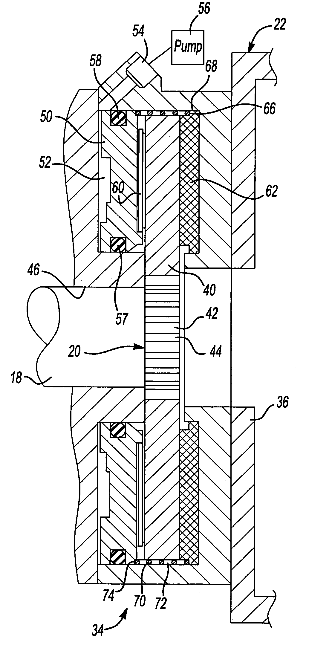
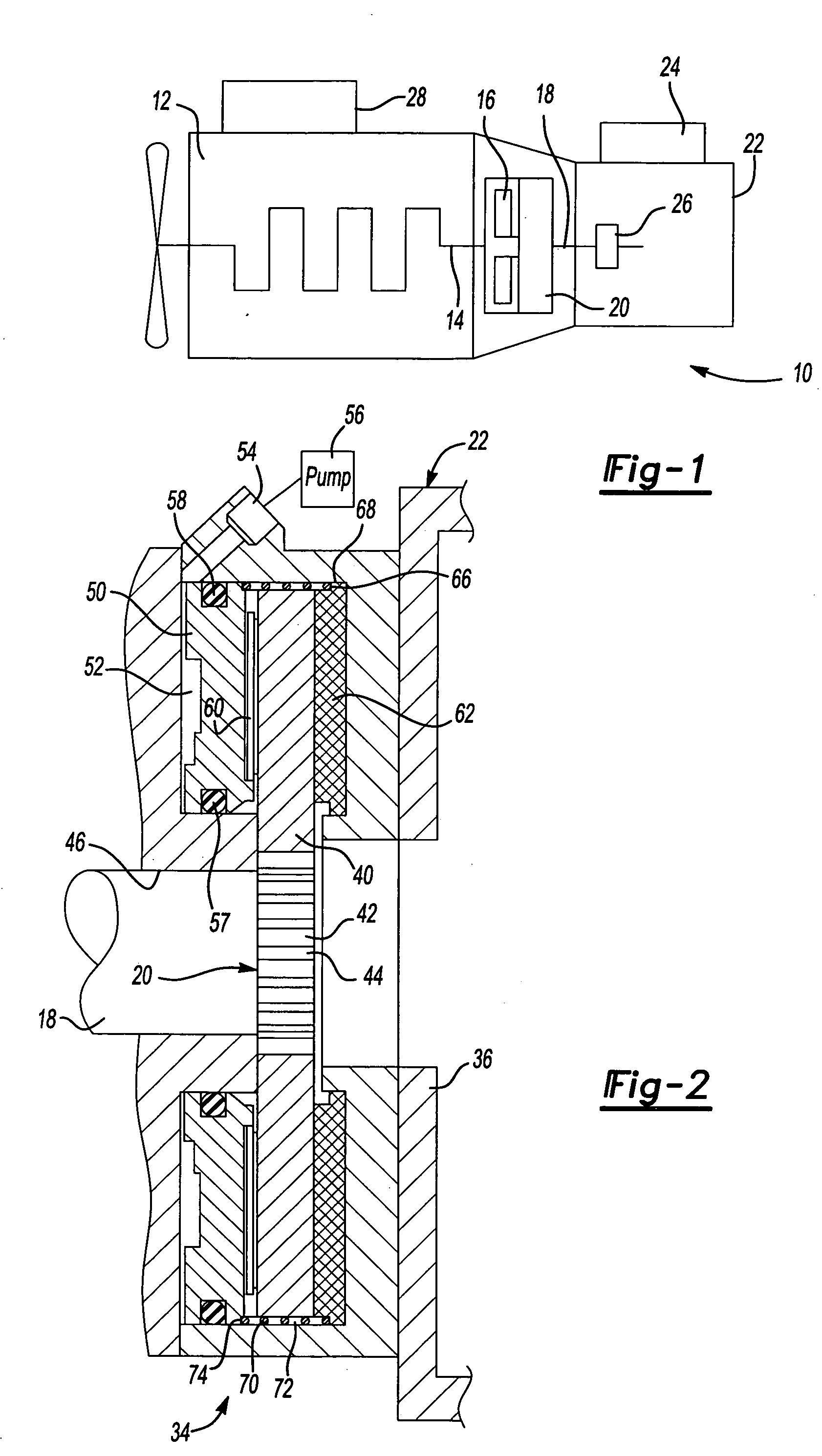
[0033] Referring to FIG. 1, a transmission system 10 for a vehicle engine 12 is schematically illustrated. The engine 12 has a crankshaft 14 that is connected through a clutch 16 to an input shaft 18. An input shaft brake 20 is assembled to the input shaft 18. The input shaft 18 is connected to a multi-speed gear transmission 22 that is controlled by a controller 24. Controller 24 monitors transmission operations and may also monitor engine operations. The controller may also obtain data from other signal sources as is well known in the art. For example, a rotation sensor 26 may be provided to monitor the speed of rotation of the input shaft 18. The controller 24 may also receive data from an engine speed tachometer or the engine controller 28. A wide variety of sensors may be used to provide data to the controller 28.

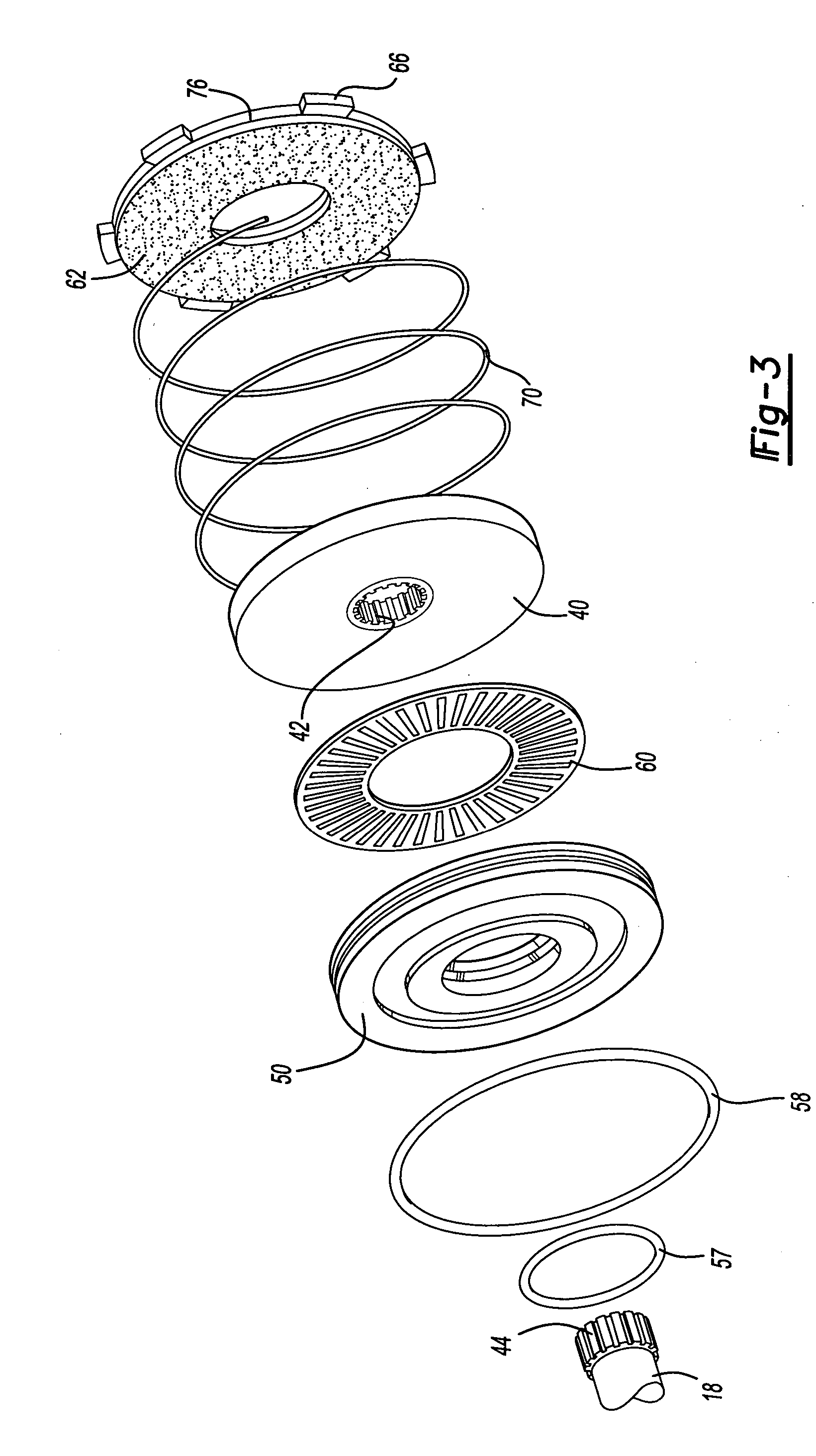
[0034] Referring to FIGS. 2 and 3, a portion of a transmission 22 is shown that is adapted to receive torque from the engine 12 via an input shaft 18. An inertia bra...


PUM


Abstract

An input shaft brake and disconnect apparatus is provided in a housing between an engine and a transmission. The disconnect apparatus has a first cavity that receives pressurized fluid causing a piston to shift and disconnect an input shaft from a clutch. Pressurized fluid is provided to a second cavity to shift a piston that is associated with a single brake disk or double brake disk that are disposed on one or both sides of an input shaft rotor that is retained on an input shaft. The disconnect apparatus and brake allow for quicker shifting.

Description

BACKGROUND OF THE INVENTION [0001] 1. Field of the Invention [0002] The present invention relates to a vehicle transmission system that has an input shaft brake and disconnect apparatus disposed between a clutch and a multiple speed gear transmission. [0003] 2. Background Art [0004] Vehicles are provided with transmissions that provide multiple gear ratios for different power and speed requirements. Many different types of transmissions have been developed, including manual transmissions, automatic transmissions and automated shift transmissions. Automatic transmissions are generally provided for cars and light trucks that provide fully automatic shifting by means of a complex hydraulic and electronic control system. Manual transmissions are simpler and generally require manual disengagement of a clutch and manual movement of a shift lever to engage different gear ratios. Automated shift manual transmissions have been developed that provide the convenience of an automatic transmissi...

Claims


Application Information

Patent Timeline
IPC IPC(8): F16D67/04
CPCF16D67/02F16D2121/02F16D2127/02F16H2003/123F16D67/04
Inventor SMITH, WADE A.REINOEHL, TROY S.SCHLOSSER, KEVIN F.
Owner EATON INTELLIGENT POWER LIMITED
Learn More