
Infinitely adjustable engagement system and method

a technology of engagement system and adjustable height, which is applied in the direction of friction lining, machines/engines, couplings, etc., can solve the problems of limited step size, limited spacing between teeth, and limited step size, etc., to achieve the effect of limiting step size and utility for high-precision applications

Inactive Publication Date: 2006-05-25
CARMAN GREGORY P +2
View PDF7 Cites 8 Cited by
  • Summary
  • Abstract
  • Description
  • Claims
  • Application Information

AI Technical Summary

Benefits of technology

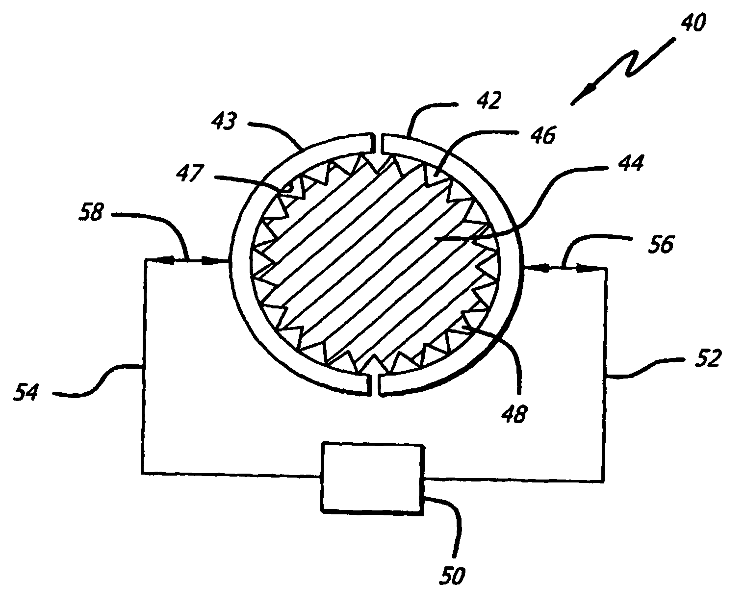
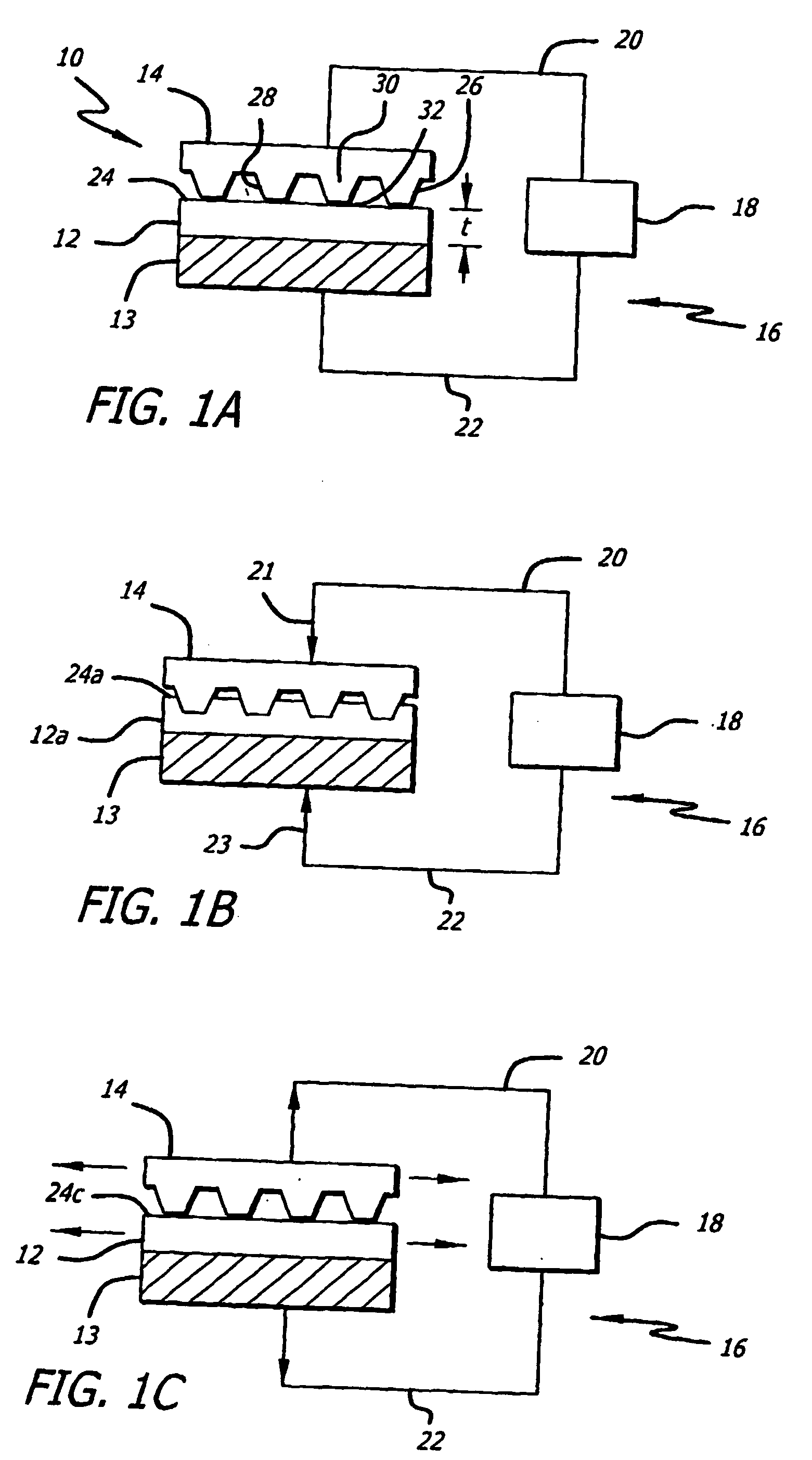
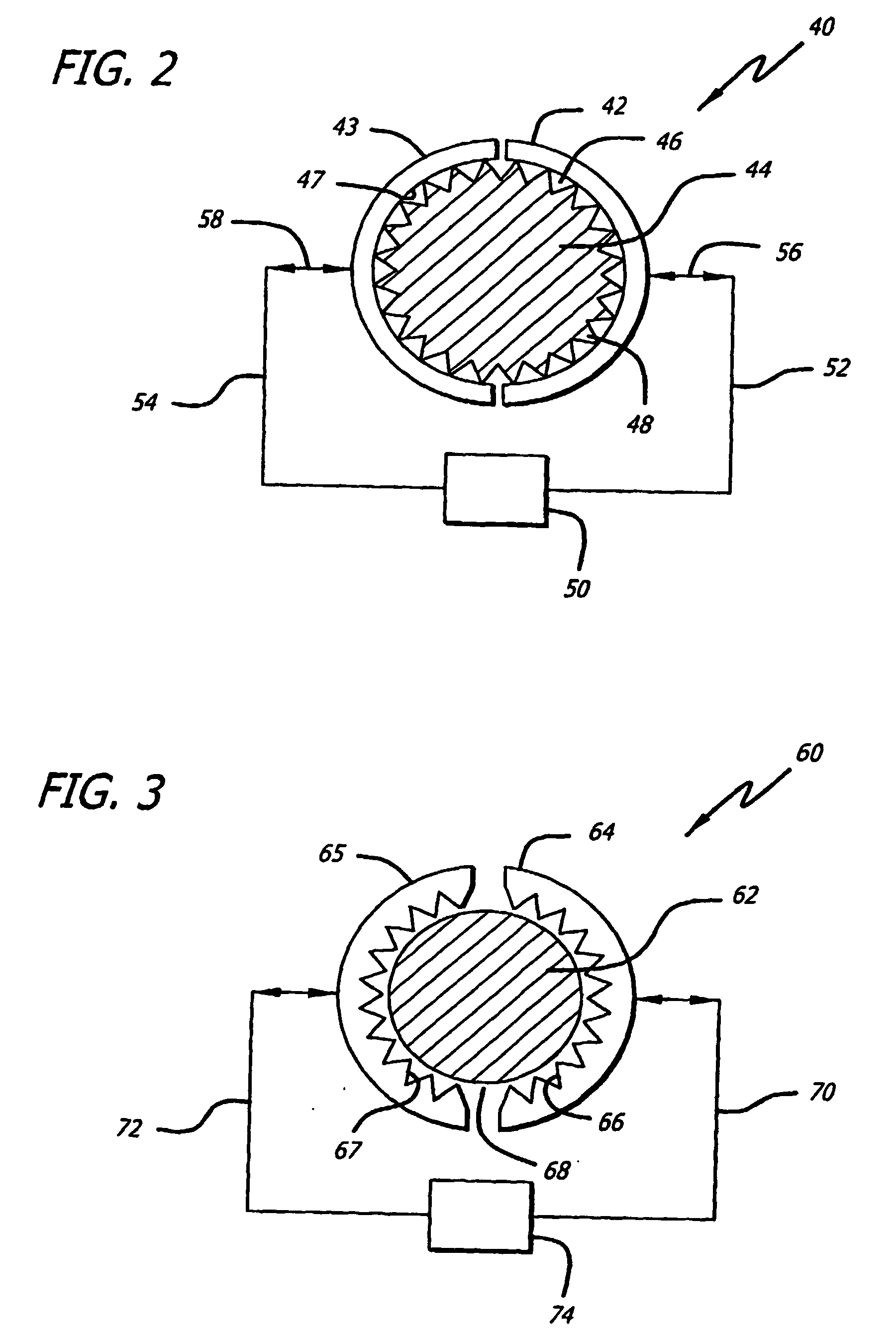
[0007] In accordance with the present invention, systems and methods are provided for releasable engagement of two bodies. The systems include a first body that has an engagement surface that is designed for engagement with the indenter surface of the second body. As a feature of the present invention, the engagement surface of the first body is made from a pseudo-elastic material that is maintained at an “operating temperature”. The operating temperature is above the martensite-austenite transition temperature of the pseudo-elastic material such that the pseudo-elastic material undergoes a conversion between the relatively hard austenite state and the relatively soft martensite state during application of stress (pressure) by the indenter. As a result, the engagement surface conforms to the indenter surface that includes one or more teeth. The penetration of the indenter teeth into the first body provides a secure and precise engagement of the two bodies.
[0008] The system includes an engagement mechanism that positions the two bodies relative to each other and provides reversible contact of the indenter surface with the engagement surface. When the indenter teeth are withdrawn from contact with the engagement surface (stress removed), the pseudo-elastic material returns to the austenite state and the engagement surface returns to its original unstressed shape. The two bodies may then be repositioned and the engagement process repeated. As a feature of the present invention, the return of the engagement surface to its original shape allows one to make extremely small movements during repositioning of the two bodies prior to re-engagement. Accordingly, the system essentially provides for an infinite degree of position adjustments.
[0009] The systems and methods of the present invention are particularly useful for engagement systems where precise positioning and / or rapid engagement and re-engagement of two bodies is required. High frequency engagement is possible because heat is not required to convert the pseudo-elastic engagement surface back to its original (non-deformed) shape. The systems and methods are well suited for use in micro systems where the indenter teeth and pseudo-elastic engagement surfaces are extremely small and capable of positioning the two engagement bodies with precision in the sub-micron range.
[0010] In addition, the use of a pseudo-elastic material provides wear resistance that increases the life of clamping or gearing mechanisms, as compared to conventional designs. Further, the invention can be utilized in gearing systems where gears (indenters) of different pitch must interact with a single gear (engagement surface).

Problems solved by technology

While this arrangement can support large lateral forces, the distance between the teeth limits step size.
Although micro-electromechanical system (MEMS) technology is helpful, teeth spacing reduction is limited, limiting step size and utility for high precision applications.
Stepping speed is also significant, and ensuring proper teeth meshing for each step is often problematic, especially at high stepping frequencies.
If teeth fail to mesh properly, damage and wear can occur, significantly reducing the effectiveness of a clamping device.
Similarly, in gearing mechanisms, two mating gears must have correct pitch, or damage can occur.
In mechanical designs, such as transmissions, two gears with dissimilar pitch often require engagement, requiring additional gears, added cost, added complexity, added weight, increased use of belts, and can cause slipping and shorten the life of gears.
However, since heating is required, it is an inherently slow process.
Such heating also requires the use of added devices, mass, adding complexity and cost.

Method used


Image

  • Infinitely adjustable engagement system and method
  • Infinitely adjustable engagement system and method
  • Infinitely adjustable engagement system and method

Examples


Embodiment Construction

[0015] Exemplary embodiments are described with reference to specific configurations. Those of ordinary skill in the art will appreciate that various changes and modifications can be made while remaining within the scope of the appended claims. Additionally, well-known elements, materials, devices, components, methods, process steps and the like may not be set forth in detail in order to avoid obscuring the invention.

[0016] The systems and methods of the present invention may be used in a wide variety of applications where precise and secure engagement of two or more bodies is required. The invention may be used in connection with linear motors (stepper, DC brushed and brushless servo, inductance and AC synchronous, etc.), gearing systems, clamping systems, medical / surgical applications, dental applications, eyeglass applications, optical applications, precision placement applications and various other applications requiring fast-acting, high holding force, infinite step size resol...


PUM


Abstract

A system for releasable engagement of two bodies where one of the bodies deforms the other body during the engagement process. The system includes a first body having an engagement surface that is made from a pseudo-elastic mater pseudo-elastic material is maintained at an operating temperature that is above the martensite-austenite transition temperature for the material. The second body has an indenter surface that contacts the pseudo-elastic material and exerts sufficient stress to convert the material from the relatively hard austenite state to the relatively soft martensite state wherein the material conforms to the indenter shape. Upon release of the indenter contact stress, the pseudo-elastic material changes back to its original shape.

Description

BACKGROUND OF THE INVENTION [0001] 1. Field of the Invention [0002] This invention relates generally to systems and methods for engaging two bodies together. More particularly, the invention involves the engagement of two bodies where, during the engagement process, one of the bodies deforms the other body. [0003] 2. Description of Related Art [0004] Clamping mechanisms are used for a variety of purposes including linear motors. One conventionally used clamping design includes locking surface teeth. While this arrangement can support large lateral forces, the distance between the teeth limits step size. Although micro-electromechanical system (MEMS) technology is helpful, teeth spacing reduction is limited, limiting step size and utility for high precision applications. Stepping speed is also significant, and ensuring proper teeth meshing for each step is often problematic, especially at high stepping frequencies. If teeth fail to mesh properly, damage and wear can occur, significan...

Claims


Application Information

Patent Timeline
IPC IPC(8): F01D5/02B81BF16D1/00F16D63/00F16D69/00
CPCF16B11/002F16D63/006Y10T403/21F16D2069/004F16D69/00
Inventor CARMAN, GREGORY P.MITROVIC, MILANPULLIAM, WADE J.
Owner CARMAN GREGORY P
Learn More