Intrinsically safe light
a technology for working lights and light sources, applied in the field of work lights, can solve the problems of requiring a relatively low amount of power and producing a low amount of heat, and achieve the effect of low amount of power and low amount of hea
- Summary
- Abstract
- Description
- Claims
- Application Information
AI Technical Summary
Benefits of technology
Problems solved by technology
Method used
Image
Examples
second embodiment
[0062] Referring to FIG. 2, a work light in accordance with the present invention is shown. Work light 48 includes handle 50 having ends 52 and 54 with power cord 56 extending from end 52. Secured to end 54 of handle 50 is transparent cover 58. A portion of cover 58 shown in FIG. 2 is broken away for illustration purposes. Handle 50 and cover 58 may be constructed by any suitable method such as injection molding or blow molding. As with handle 24 and cover 26 of work light 22, handle 50 may be formed from any suitable material including plastic or metal. The material used for cover 26 may also be any suitable material including plastic or glass. Disposed at both ends of cover 58 are rubber bumpers 60 which are designed to protect work light 48 from damage if the light were dropped, for example. Cover 58 is provided with a plurality of transparent dome shaped or convex lenses 59. One lens 59 is located directly above each LED 20 to magnify and focus the light emitted therefrom. Lens ...
third embodiment
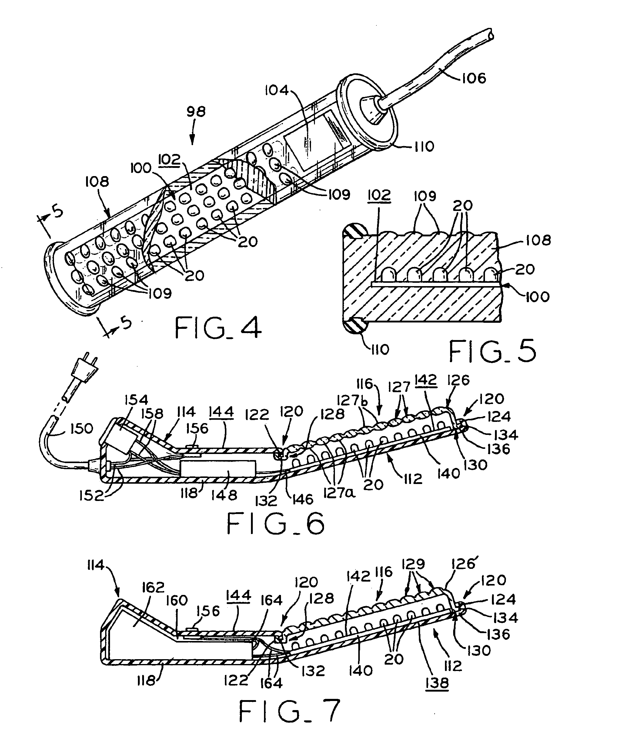
[0064]FIGS. 4 and 5 disclose a work light in accordance with the present invention. Submersible work light 98 includes circuit board 100 having a plurality of LEDs 20 mounted on surface 102 thereof in the same manner as discussed above. Power regulator 104 is disposed at one end of circuit board 100 to transform the input voltage from the power source into the appropriate operating voltage for LEDs 20 and circuit board 100 of which they are a part. In this embodiment, the input power is 120 volts from an electrical outlet through power cord 106. Solid, transparent casing 108 is molded around circuit board 100, LEDs 20, power regulator 104, and the end of cord 106. Rubber bumpers 110 are secured to each end of casing 108 to protect work light 98 from damage. Casing 108 is molded about circuit board 100, LEDs 20, power regulator 104, and the end of cord 106 to allow work light 98 to be submersible or waterproof. The material used to encase the components of work light 98 may be of any...
fourth embodiment
[0065] a work light in accordance with the present invention is illustrated in FIGS. 6 and 7. Work light 112 includes handle portion 114 and light head portion 116 which is disposed at a slight angle relative to handle portion 114. Work light 112 is constructed such that casing 118 completely surrounds handle portion 114 and extends along the backside of light head portion 116. Casing 118 may be constructed from any suitable material including plastic or metal by any suitable method such as molding. Terminating ends 120 of casing 118 are molded to define hook-like projections 122 and 124. Transparent cover 126 is positioned over circuit board 140 carrying LEDs 20 and has ends 128 and 130. Cover 126 may be plastic, glass, or the like which is formed by any suitable method. End 128 is C-shaped such that hook-like projection 122 fits into space 132 formed by the C-shaped end. End 130 is L-shaped such that leg 134 of end 130 engages space 136 of hook-like projection 124. The connections...
PUM
 Abstract
Description
Claims
Application Information
 - R&D
- Intellectual Property
- Life Sciences
- Materials
- Tech Scout
- Unparalleled Data Quality
- Higher Quality Content
- 60% Fewer Hallucinations
Browse by: Latest US Patents, China's latest patents, Technical Efficacy Thesaurus, Application Domain, Technology Topic, Popular Technical Reports.
© 2025 PatSnap. All rights reserved.Legal|Privacy policy|Modern Slavery Act Transparency Statement|Sitemap|About US| Contact US: help@patsnap.com


