
Multiple barrier biological treatment systems

a biological treatment system and multi-barrier technology, applied in biological water/sewage treatment, filtration separation, separation processes, etc., can solve the problems of reducing the cost of sbr's annual operation and maintenance, so as to reduce the cost of sbr's and reduce the cost of construction. , the effect of improving the cost effectiveness of sbr systems

Inactive Publication Date: 2006-05-25
AQUA AEROBIC SYST
View PDF27 Cites 17 Cited by
  • Summary
  • Abstract
  • Description
  • Claims
  • Application Information

AI Technical Summary

Benefits of technology

The invention separates the activated sludge and biochemical reaction stages of batch treatment from the clarification and sedimentation stages, allowing for greater flexibility and effectiveness in treating wastewaters. This separation can be achieved through various methods, such as constructing separate basins or installing baffles. The invention also allows for independent operation of the clarification and sedimentation stages, leading to higher effluent water quality. Overall, the invention provides greater operational flexibility, treatment effectiveness, cost savings, and improved biochemical reaction time and oxygen utilization rates.

Problems solved by technology

In an SBR system, a single vessel performs multiple functions over time, thereby placing all the necessary treatment equipment within a smaller footprint, saving the cost of purchasing and maintaining additional land.
In addition, both the initial capital costs and the annual operation and maintenance cost for SBR's are ordinarily lower than continuous flow systems since there are fewer vessels to maintain and fewer pieces of equipment to install and operate.
The inability to aerate a vessel continuously means that, maximum oxygen utilization rates cannot be accommodated in small reaction tanks.
However, the turn down ratio is limited to a fixed fraction of the full volume.
The rising and falling water line makes it more difficult to remove floatable pollutants like oils and greases (generically referred to as “scum”) in comparison to a vessel that operates at a fixed water level.

Method used


Image

  • Multiple barrier biological treatment systems
  • Multiple barrier biological treatment systems
  • Multiple barrier biological treatment systems

Examples


Embodiment Construction

[0031] Set forth below is a description of what are currently believed to be the preferred embodiments or best examples of the inventions claimed. Future and present alternatives and modifications to these preferred embodiments are contemplated. Any alternatives or modifications which make insubstantial changes in function, in purpose, in structure or in result are intended to be covered by the claims of this patent.

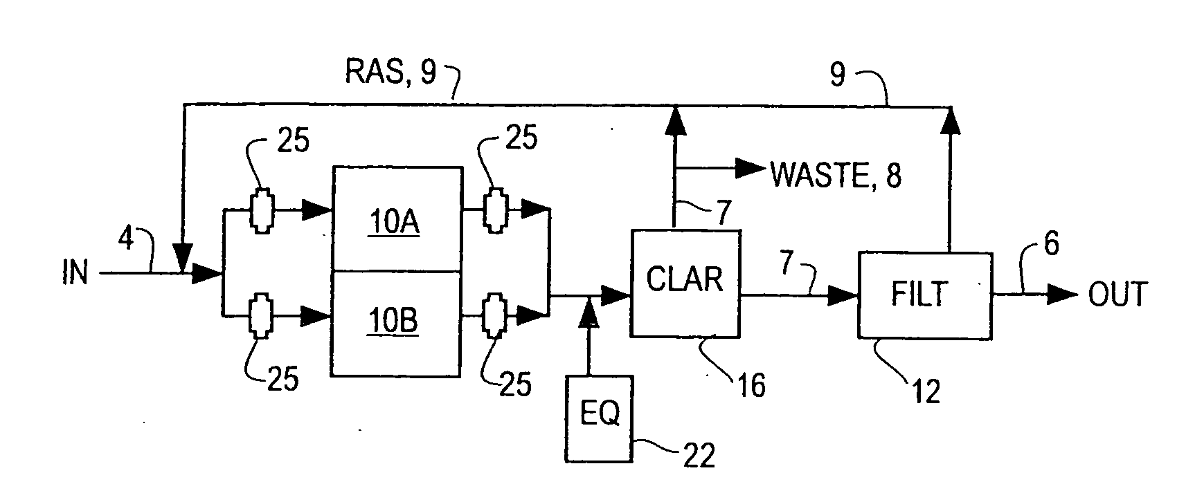
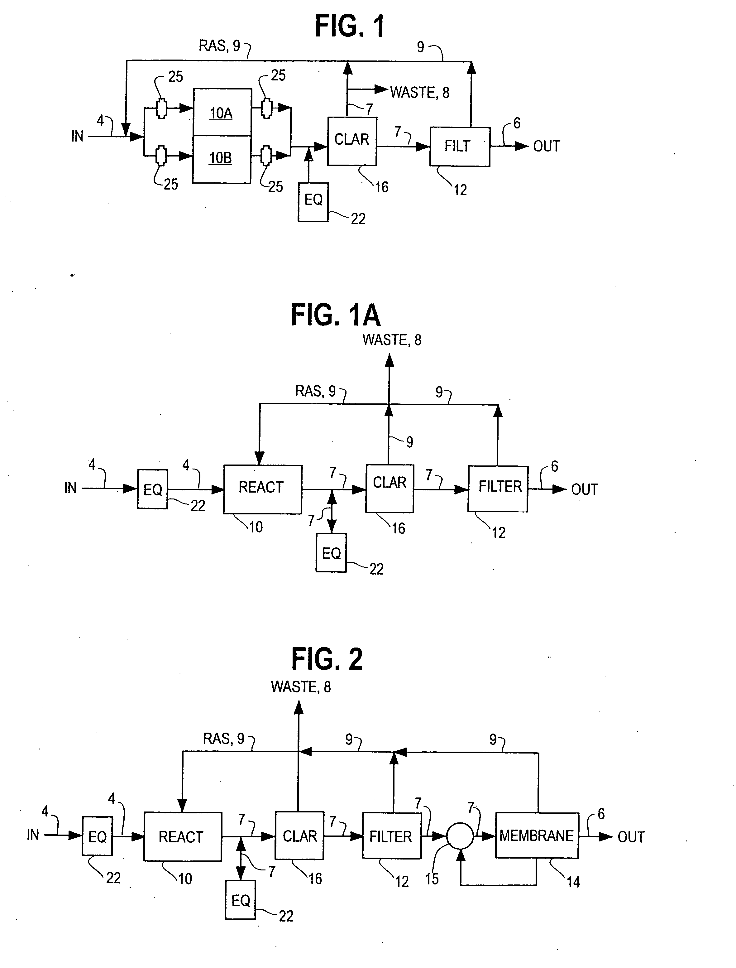
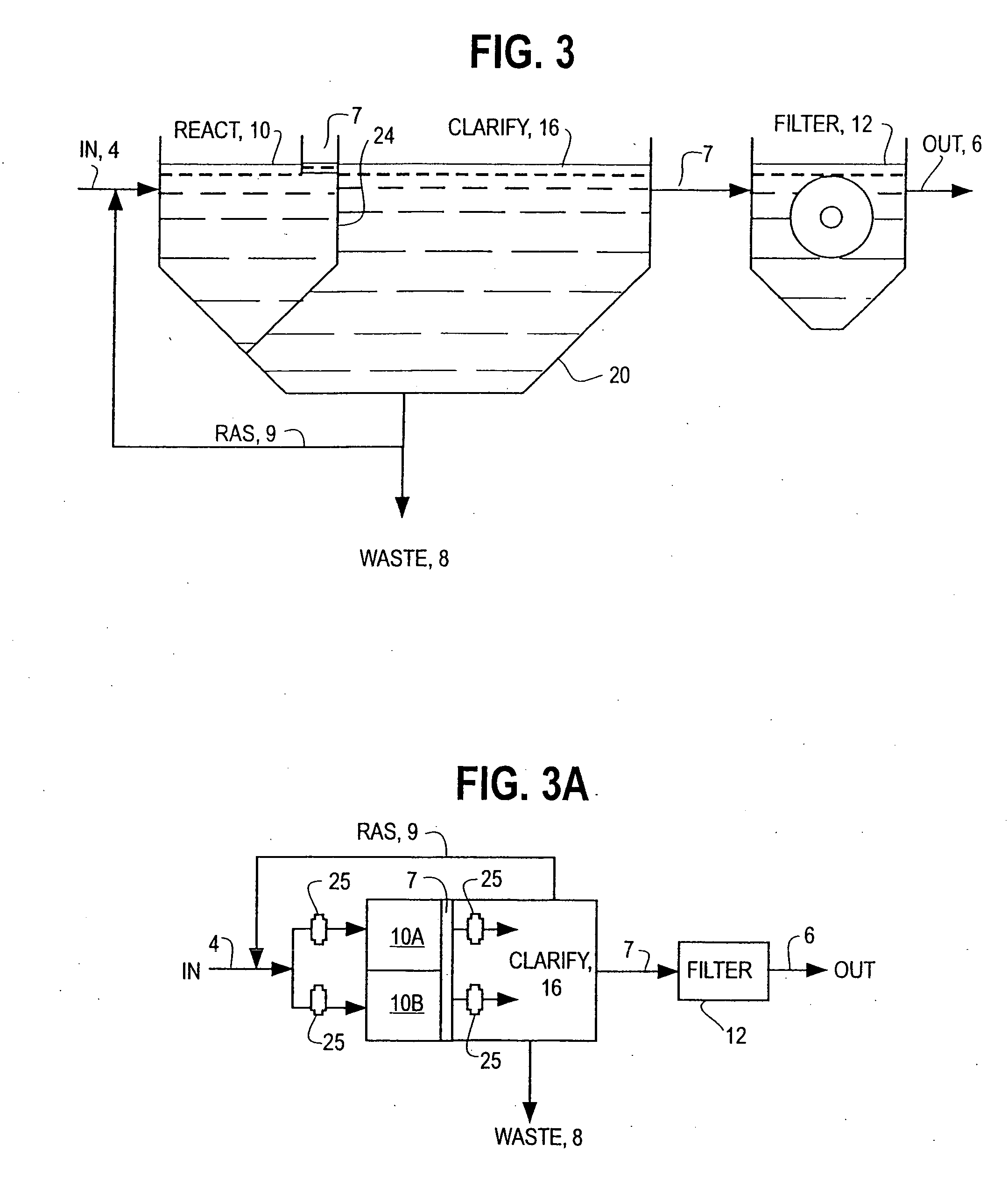
[0032]FIGS. 1, 3 and 3A show an SBR modified according to one of the preferred embodiments of the present inventions having separate basins for biochemical reaction and clarification, with the biochemical reaction basin 10 also being divided into two biochemical reaction basins 10A and 10B. The influent can be a raw wastewater influent, but is more commonly the effluent from a previous treatment step such as screening, chemical conditioning or other primary treatment processes as are known in the art. The influent channel 4 conveys the wastewater into a biochemical reac...


PUM

PropertyMeasurementUnit
particle sizesaaaaaaaaaa
volumeaaaaaaaaaa
sizeaaaaaaaaaa

Abstract

The inventions separate the activated sludge, biochemical reaction stages of the batch treatment process of a sequencing batch reactor from the clarification and sedimentation stages by separating the locations where each process takes place. The separation may be accomplished in a variety of ways including constructing separate basins for each process, installing baffles or other partitions in a single vessel to isolate the areas where each process takes place, or other methods of process separation as are known in the art. In each process, treatment occurs through the performance of a series of operations. The operations are repeated for each batch of wastewater processed by the SBR. In a conventional SBR process, the cycle of operations for clarification and sedimentation are dependent on a preceding biochemical reaction step. However, in the present invention the clarification and sedimentation operations are independent of the biochemical reaction operations. It remains possible to coordinate operations so that the process cycles are coincident, however the benefits of the invention are more readily realized by the practice of independent operation.

Description

FIELD OF THE INVENTION [0001] The present inventions apply generally to batch mode wastewater treatment processes and systems that employ activated sludge. More specifically, the inventions are directed to enhanced removal of suspended solids and other pollutants from a fluid stream using a modified sequencing batch reactor configuration. BACKGROUND OF THE INVENTION [0002] When a wastewater treatment facility is designed to employ batch mode influent flow treatment with a sequencing batch reactor (or SBR), the treatment plant operator realizes several advantages over the use of conventional, continuous flow treatment facilities. In an SBR system, a single vessel performs multiple functions over time, thereby placing all the necessary treatment equipment within a smaller footprint, saving the cost of purchasing and maintaining additional land. In addition, both the initial capital costs and the annual operation and maintenance cost for SBR's are ordinarily lower than continuous flow ...

Claims


Application Information

Patent Timeline
Patent Type & Authority Applications(United States)
IPC IPC(8): C02F3/12
CPCC02F3/1263Y02W10/10
Inventor JOHNSON, LLOYD W.MIKKELSON, KENNETH A.GLEASON, DENNIS M.LANG, EDWARD W.
Owner AQUA AEROBIC SYST
Learn More