
Method and apparatus for improving measuring accuracy in gas monitoring systems

a technology of gas monitoring system and measuring accuracy, which is applied in the direction of gas analyser construction details, material electrochemical variables, and analysis of gaseous mixtures. it can solve the problems of increasing the incidence of defects, reducing device yield, and only filtration and measurement of ammonia in photolithographic processes. achieve accurate and repeatable measurement, facilitate the effect of monitoring such species

Inactive Publication Date: 2006-05-25
ENTEGRIS INC
View PDF10 Cites 272 Cited by
  • Summary
  • Abstract
  • Description
  • Claims
  • Application Information

AI Technical Summary

Benefits of technology

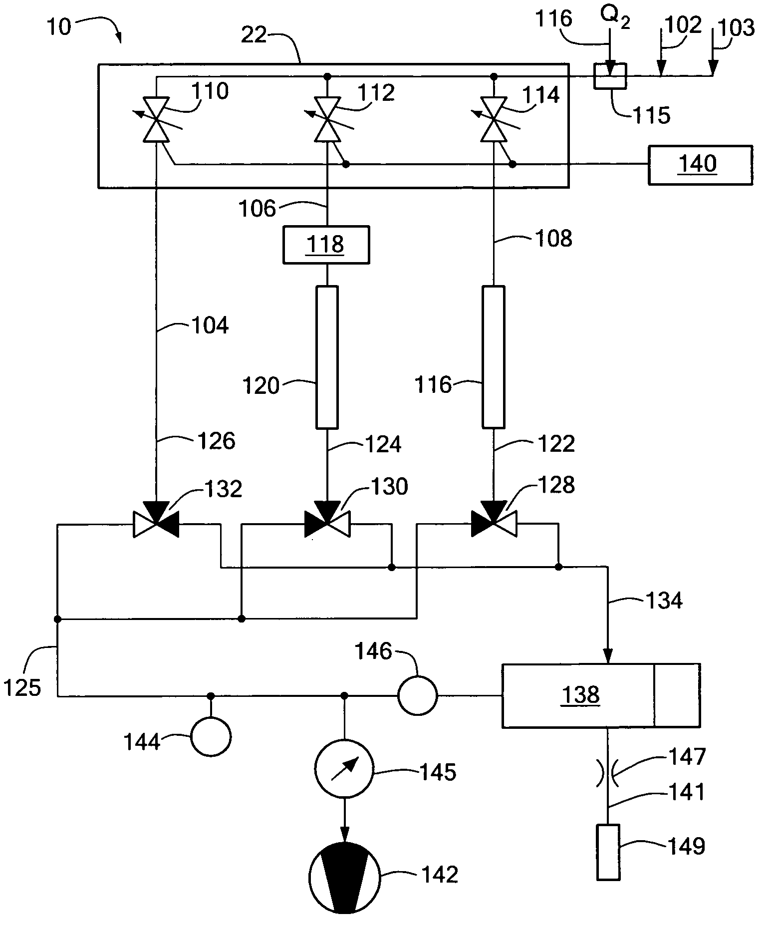
[0007] The present invention provides systems and methods for monitoring contaminants such as gas-phase basic nitrogen-containing species in gas streams for example, from one or more sampling sites that facilitate the monitoring of such species at low concentration. In preferred embodiments, the systems and methods of the present invention monitor a plurality of sampling sites using a substantially constant gas pressure. A variable orifice valve system is used to control fluid flow from the sampling location to maintain a constant pressure in the flow path to the detector system. In a preferred embodiment a selected channel controls the flow rate and one or more unselected channels are used to control pressure. This provides a more accurate and repeatable measurement of the trace contaminants frequently formed in ambient gases used in semiconductor fabrication equipment.

Problems solved by technology

In semiconductor manufacturing processes even low concentrations of airborne molecular contaminates can reduce device yields and increase the incidence of defects.
As a result, the filtration and measurement of ammonia only is not satisfactory to photolithographic processes that are affected by low concentrations of basic nitrogen-containing species, such as photolithography using chemically amplified DUV, because ammonia is typically not the only basic nitrogen-containing airborne contaminant present.
In addition, measurement of only the total fixed nitrogen species present is also not sufficient because many typical contaminant species (for example, HCN, NO, NO2) are not basic in nature and do not significantly affect the photolithography process.
A problem associated with such filtering systems has been to accurately predict the remaining life of filtering media used in the system so that filters can be changed at appropriate times with minimal disruption to the use of the expensive production facility.
One problem of this approach is that it replaces filters after a “failure” has already occurred with the concomitant loss in yield and increase in defects.
A problem associated with this approach is that filters may be replaced prematurely, incurring unnecessary filter replacement costs and unnecessary downtime of the facility.
Another problem of this approach is that the estimated filter lifetimes may be too long, resulting in filter failure before replacement and process contamination.
However, harmful contamination concentrations can be very low, for example, in the ppb range for NMP and ammonia in deep ultraviolet (DUV) photolithography; and reliably monitoring such low concentrations has traditionally been problematic.
The measurement of ppb level or less concentrations presents still further problems.
For example, fluctuations in the conductance (C) of a gas sample flow path can add significant error to a concentration measurement, which can be compounded if the concentration of a species of interest is determined from differencing or adding two or more concentration measurements.
Measurement errors such as these can lead to interferences that create spurious signals and act as noise contributions to data being measured.
Changes in flow path conductance can become more problematic as the length of a flow path increases.
In addition, where the concentration of a species of interest is determined from differencing or adding two or more concentration measurements, and such measurements use different flow paths (for example, within the gas monitor); differences in the conductance between the flow paths can add additional error to the concentration value of the species of interest.

Method used


Image

  • Method and apparatus for improving measuring accuracy in gas monitoring systems
  • Method and apparatus for improving measuring accuracy in gas monitoring systems
  • Method and apparatus for improving measuring accuracy in gas monitoring systems

Examples


Embodiment Construction

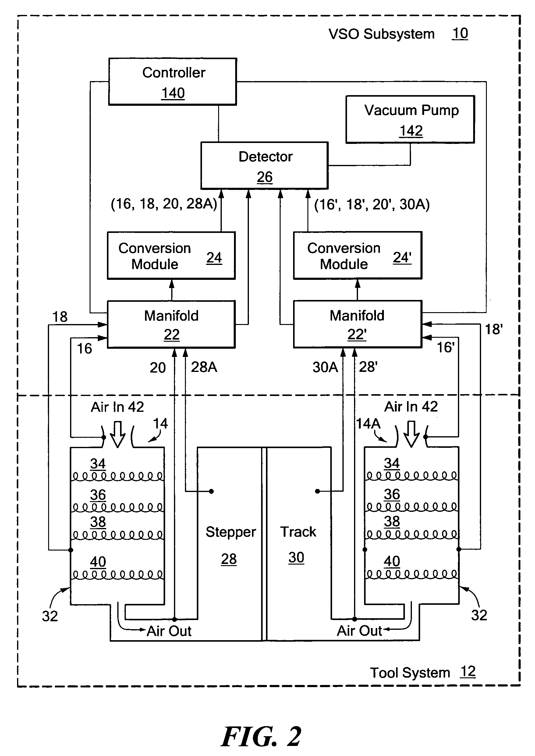
[0023] Embodiments disclosed herein regulate the flow rate of a gas sample to a detector by controlling the size of one or more variable orifices in the flow path of the gas sample to the detector. In an embodiment, a gas sampling subsystem employs one or more variable orifices in the flow path to regulate gas flow such that during detector measurements, the gas flow rate varies by less than about 0.5% from a target flow rate. In preferred embodiments, these variable orifices can comprise voltage sensitive orifices (VSO's). At substantially the same time, one or more VSO's outside the flow path of a gas sample flowing to the detector regulate the pressure of the gas sample being measured in the detector such that during detector measurements the pressure of the gas sample in the detector varies by less than about 0.5% from a target pressure. In this embodiment, substantially constant flow and pressure can be maintained independent of the length of the gas sample line being measured....


PUM


Abstract

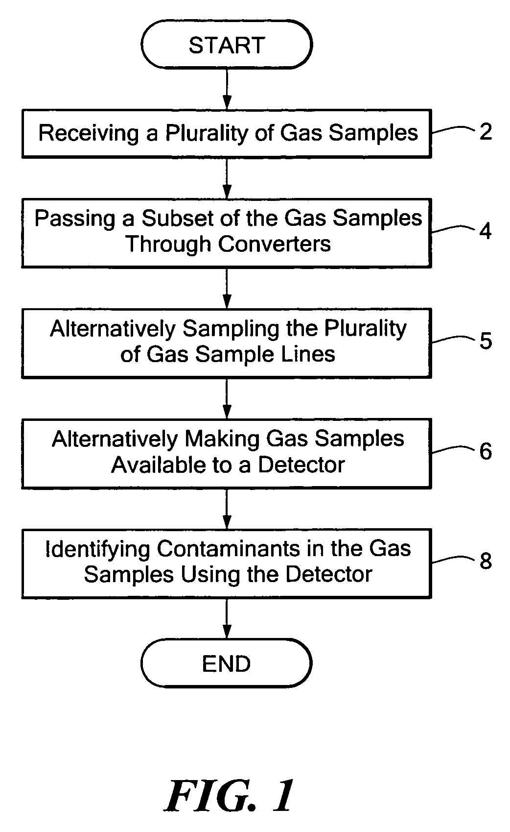
A method and apparatus for improving measurement accuracy in a gas monitoring system is provided. The apparatus can be connected to a plurality of gas sample lines each containing a gas sample. The gas samples are routed through a number of delivery channels which are fewer in number than the plurality of sample lines. Each delivery channel is alternatively coupled to a detector which identifies contaminants present in the gas samples. Each delivery channel includes a voltage sensitive orifice (VSO). The VSO's are operated by a controller and provide gas samples at a constant flow and a constant pressure to the detector independent of the length of the gas sample line being measured.

Description

BACKGROUND OF THE INVENTION [0001] In semiconductor manufacturing processes even low concentrations of airborne molecular contaminates can reduce device yields and increase the incidence of defects. For example, concentrations of gas-phase amines, such as ammonia (NH3) and n-methyl-2-pyrrolidinone (NMP), at part-per-billion (ppb) levels can react with photoresists and lead to “T-topping.” These semiconductor manufacturing processes are sensitive to NMP, ammonia, or other amines, as well as being sensitive to the total proton-bonding capability of all nitrogen-containing base contaminants present, regardless of the specific identity of the amine contamination. As a result, the filtration and measurement of ammonia only is not satisfactory to photolithographic processes that are affected by low concentrations of basic nitrogen-containing species, such as photolithography using chemically amplified DUV, because ammonia is typically not the only basic nitrogen-containing airborne contam...

Claims


Application Information

Patent Timeline
IPC IPC(8): G01N27/26
CPCG01N33/0009
Inventor GOODWIN, WILLIAMPHELPS, MARKLOBERT, JURGEN MICHAELLAQUIDARA, BRUCEGRAYFER, ANATOLY
Owner ENTEGRIS INC
Learn More