
Method and apparatus for automated pre-treatment and processing of biological samples

Active Publication Date: 2006-05-18
AGILENT TECH INC
View PDF83 Cites 166 Cited by
  • Summary
  • Abstract
  • Description
  • Claims
  • Application Information

AI Technical Summary

Benefits of technology

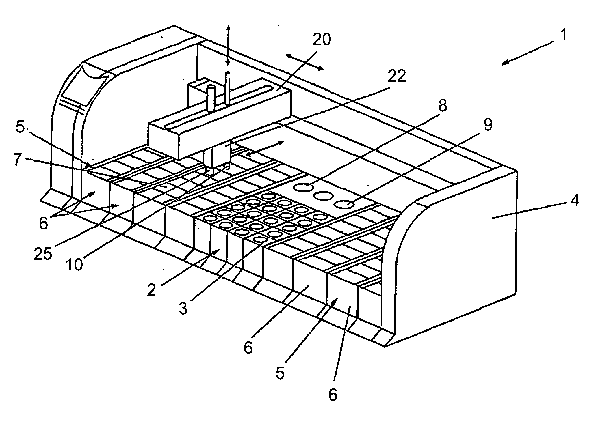
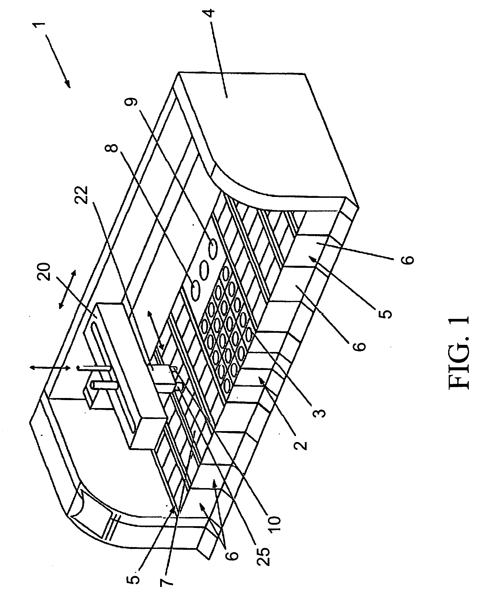
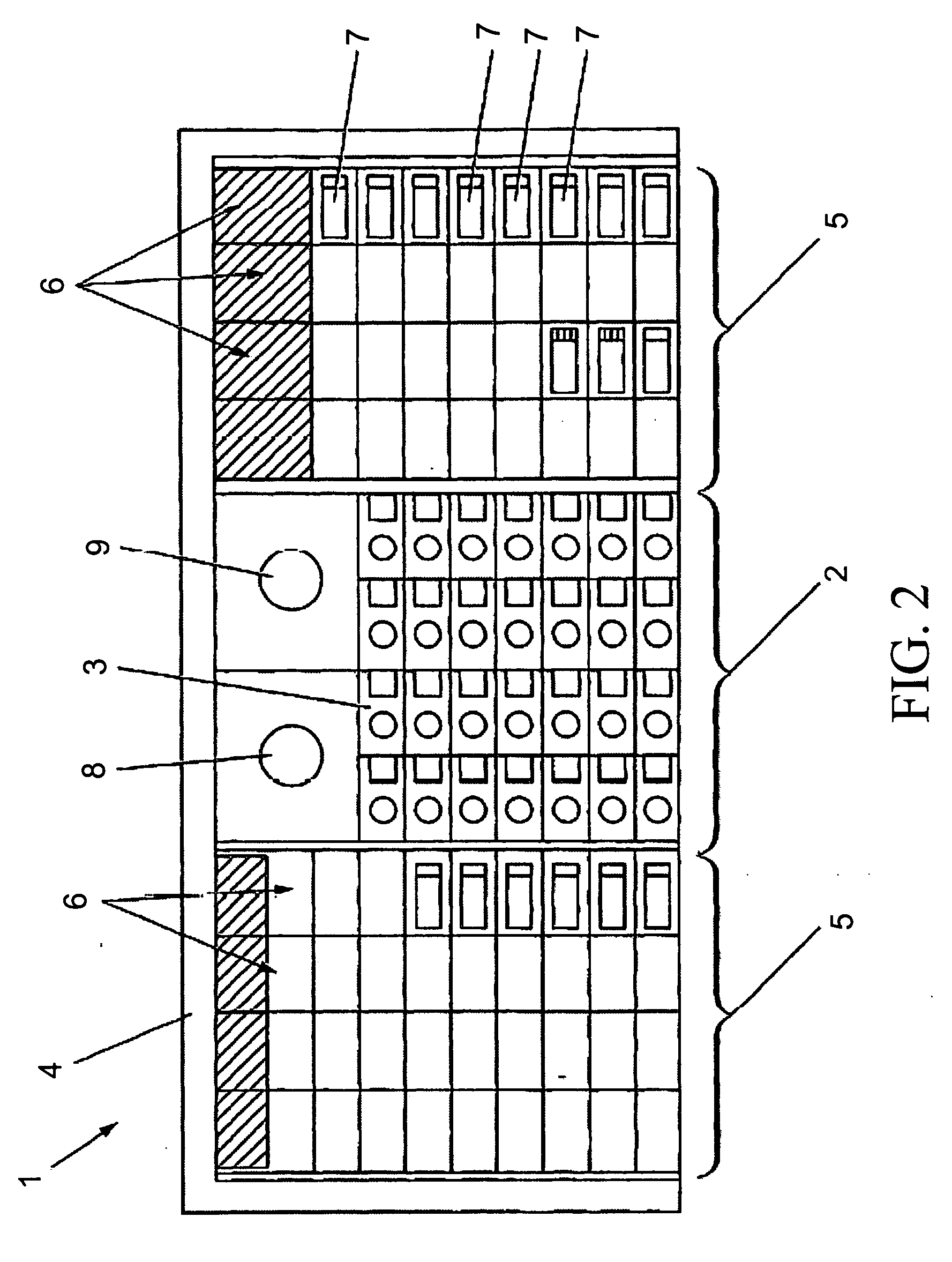
[0031] Preferably, the invention further comprises probe drive means arranged for moving a probe, wherein the probe drive means is arranged to aspirate a portion of reagent from a selected reagent container, such as a bottle or vial, of the reagent section by means of a probe and to apply reagent to a selected carrier means. The probe drive means may be a robot arm with two or three degrees of freedom, such as an articulated arm or one track or a set of perpendicular tracks along which a probe retainer of the probe drive means may be displaced, wherein the probe retainer may be moved in a direction normal to the track or tracks. The skilled person may readily design other types of probe drive means, e.g. combinations of the above described.
[0070] An automated sample processing system according to the various embodiment of the present invention may greatly improve operation of automated sample processing from several perspectives. It may act to accept changes to the system while operating and may automatically adapt to a change in the aggregate events originally scheduled. It also may provide a better approach to just how such scheduling may occur as well as providing a user opportunities to undo a change, such as when its effect is undesirable. The system may also provide for automatic suggestions to permit an operator to more optimally enhance the schedules on which events occur.

Problems solved by technology

Previously, in some applications, these steps may have been performed manually, potentially creating a time-intensive protocol and necessitating personnel to be actively involved in the sample processing.
However, such previous efforts may have not fully addressed the needs for an automated sample processing system.
Such prior efforts to automate sample processing may be deficient in several aspects that prevent more robust automated sample processing, such as: the lack of sufficient computer control and monitoring of sample processing; the lack of information sharing for processing protocol and processing status, especially for individual samples; the lack of diagnostic capabilities; and the lack of real-time or adaptive capabilities for multiple sample batch processing.
The staining procedure is laborious and uses many different reagents.
Methods for mixing reagents and liquids are well known—but several aspects are important in the context of IHC and ISH instruments wherein the mixing in some processes can be cumbersome.
Unfortunately, during the mixing, several problems may arise.
Some problems arise due to the complex use of reagents in the staining procedure.
Furthermore, the resulting mixtures are unstable over time and need to be used within a short time.
Many proteins cannot easily tolerate to be exposed to the hydrophobic air in foam.
The foam can spread to other compartments of the instrument in an unwanted and unpredictable way.
Mixing of some reagents like e.g. the HRP chromogens and peroxide reagents can result in the formation of small bubbles.
Some of the reagents or buffers are incompatible with each other.
In the event of cross contamination due to e.g. carry over, the reagents may be ruined within seconds or solids can precipitate, making the staining unsuccessful.
For example, enzyme containing reagents can not be mixed with the corresponding chromogens, or high salt concentrates may not be mixed with e.g. proteins containing mixtures, or organic solvents can not be mixed with protein containing mixtures, or highly pH buffered wash buffers can not be mixed with low buffered mixtures without significantly altering the properties of the reagents.
As the procedures are very complex, and the instrument uses many different protocols, one cannot predict the result of reagent carry-over or unplanned mixing of reagents.
During staining, build-up of small fouling layers on the various surfaces will rapidly cause problems, as the typical staining protocol calls for many mixing and dilution steps.
No present mixing system for automated biological sample processing apparatus truly fulfills the above-mentioned properties.
On-the-slide mixing does not allow for very large ratios of dilution.
Neither does it allow for efficient mixing of reagents with very different densities or viscosities.
However, each of these traditional sample processing systems may lack a desired degree of temperature control or temperature tolerances.
Inadequacies in temperature control of traditional technologies may include uncontrolled cooling.
Traditional systems may only provide ambient cooling when the heating devices are off.
Ambient cooling is not considered active control and may not meet protocol temperature requirements or may not otherwise be optimal.
Although heating and heat control may be features of such systems, controlled cooling of the samples, sample carriers, and processing environments may not always be adequately addressed.
However, these devices can lack sufficient capabilities of temperature control to meet certain protocol requirements, especially temperature tolerances for samples, sample carriers, reagents, and ambient system temperature.
Traditional systems may even lack temperature control, perhaps as related to temperature tolerances generally, as such tolerances may not be adequately maintained during ambient or other traditional cooling, or during processing sequences or events, generally.
In some protocols, for example, the temperature tolerances during non-heating periods may be such that uncontrolled temperature changes may produce undesirable results during the processing sequence.
Other IHC processes of the protocol may be adversely affected by uncontrolled temperature changes, the degree of temperature change, and temperature changes outside of preferred tolerances.
The lack of temperature control may actually dissuade technologists from employing automated processing sequences or protocols, especially IHC sequences, that may be dependent upon a particular temperature tolerance and the amount of temperature change during a processing sequence.
Certain types of temperature control may not have even been addressed in traditional sample processing system technologies.
Reagents, for example, can have a certain shelf life that may be limited if maintained at undesirable temperatures such as the typical ambient temperatures of traditional biological sample processing systems and the laboratories housing such systems.
Traditional technologies may lack the temperature control needed to optimally preserve the reagents stored in the processing system that are often subject to inadequate or changing ambient temperatures of such systems and the laboratory environment.
Past efforts at automated sample processing for samples presented on carriers such as slides, such as U.S. Pat. No. 6,352,861 and U.S. Pat. No. 5,839,091, have not afforded the various advantages and other combinations of features as presented herein.
Even though automated biological staining apparatuses are known in the prior-art, these conventional apparatuses do not provide for sample pre-treatment.
Unfortunately, however, this manual preparation is cumbersome and the pre-treatment may be insufficient, since it is critical that the amount of time and the temperature of the liquid must be observed very precisely in order to achieve the correct pre-treatment result.
However this instrument does not provide a processing tank for pre-treatment of the slides.
However, this does not sufficiently protect the laboratory environment in which the apparatus is placed from being contaminated with toxic material.
This increases the risk of vaporizing reagents which then may escape to the outside of the apparatus.
In this known technique, one risk is the drying out of slides and lack of control of airspeed and temperature.

Method used


Image

  • Method and apparatus for automated pre-treatment and processing of biological samples
  • Method and apparatus for automated pre-treatment and processing of biological samples
  • Method and apparatus for automated pre-treatment and processing of biological samples

Examples


example

[0147] In a preferred embodiment, the inner diameter of the tubing 701 is about 1.5 mm. In one embodiment, the probe shall be able to aspirate a volume of about 2.5 ml. Accordingly, the length of the tubing 701 has to be about 1.5 m. Such length may be accommodated / achieved by including a coil section having about 20 windings and a diameter of about 20 mm providing for about 1260 mm. By adding thereto the length of the rigid probe member and the tubing section from the coil to the fitting 706, a total of 1.5 m of tubing may be obtained. Obviously, the tubing 701 may be designed to accommodate other fluid volumes. The inner diameter of the tubing is determined such that the viscosity of the fluid will secure the fluid in the probe during the movement of the probe from reagent container to a mixer and / or a slide.

[0148] Preferably, the robotic head is adapted to lower the probe 10 when it is aligned on top of a selected reagent container. In a preferred embodiment, a reagent container...


PUM

PropertyMeasurementUnit
Fractionaaaaaaaaaa
Fractionaaaaaaaaaa
Timeaaaaaaaaaa

Abstract

The present invention concerns a method and apparatus for automatic processing a biological sample on a carrier, perhaps robotically, by applying predetermined amounts of reagents in a predetermined sequence according to a processing protocol, the processing including pre-treatment steps, under the control of an adaptive processing control system using a sample process parameter input that may be independent and an independent process parameter memory that does not interrupt process operation when being used, such that samples may be added or removed without interrupting the processing of other samples. Also included is an image capture function for sample and reagent identification and process monitoring, as well as temperature regulation and environmental control functions.

Description

CROSS REFERENCE TO RELATED APPLICATIONS [0001] This application is a continuation-in-part of co-pending international application PCT / DK2003 / 000877, titled “Method and Apparatus for Pretreatment of Biological Samples” having an international filing date of Dec. 15, 2003 and designating the United States of America; is also a continuation-in-part of co-pending international application PCT / DK2003 / 000911, titled “An Automated Sample Processing Apparatus and a Method of Automated Treating of Samples and Use of Such Apparatus” having an international filing date of Dec. 19, 2003 and designating the United States of America; is also a continuation-in-part of co-pending international application PCT / US2003 / 040518, titled “A Method and Apparatus for Automatic Staining of Tissue Samples” having an international filing date of Dec. 19, 2003 and designating the United States of America; is also a continuation-in-part of co-pending international application PCT / US2003 / 040880, titled “Systems a...

Claims


Application Information

Patent Timeline
IPC IPC(8): C12Q1/68G06F19/00C12M1/34
CPCB01L3/508Y10T436/12B01L9/06B01L2200/025B01L2200/16B01L2300/021B01L2300/0822B01L2300/1822G01N1/312G01N35/00029G01N35/00871G01N35/0092G01N35/0095G01N35/0099G01N35/1002G01N35/1004G01N35/1011G01N2035/00356G01N2035/00366G01N2035/00445G01N2035/00455G01N2035/00534G01N2035/00633G01N2035/00673G01N2035/00752G01N2035/00861G01N2035/00881G01N2035/102G01N2035/1058Y10T436/11Y10T436/2575Y10T436/112499B01L7/00Y02A90/10
Inventor FAVUZZI, JOHN A.BUCHANAN, KRISTOPHER S.BARBER, MICHAEL T.BLAND, LOREN L.ROHRBACKER, DAWN M.CLARK, ROBERT M.FEINGOLD, GORDON A.GUGGENHEIMER, BENNO M.KEY, MARC E.MARTIN, MERRITT M. JR.LATHROP, ROBERT L.RAU, JEFFERY J.SWEDA, JONATHAN R.SWEET, DOUGLAS F.VAN BOSCH, JOHN E.WINTHER, LARSWELCHER, ROSANNE
Owner AGILENT TECH INC
Learn More