
Counter electrode for dye sensitizing solar cell, and dye sensitizing solar cell having same

Inactive Publication Date: 2006-05-18
ENPLAS CORP
View PDF3 Cites 12 Cited by
  • Summary
  • Abstract
  • Description
  • Claims
  • Application Information

AI Technical Summary

Benefits of technology

[0011] It is therefore an object of the present invention to eliminate the aforementioned problems and to provide an inexpensive counter electrode for a dye sensitizing solar cell having a high photoelectric transfer efficiency even if a conductive catalytic material film is thin, and a dye sensitizing solar cell having the counter electrode.
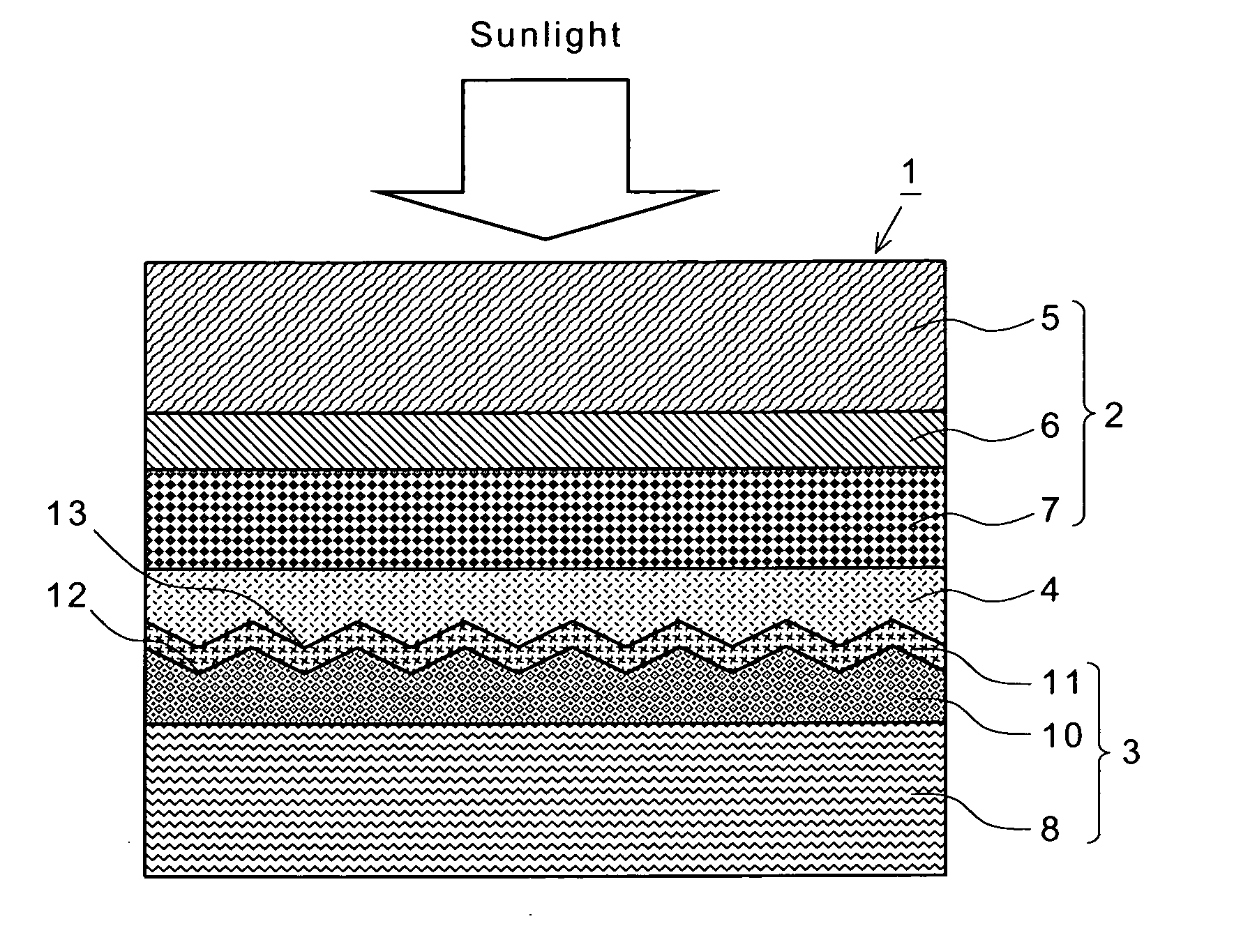
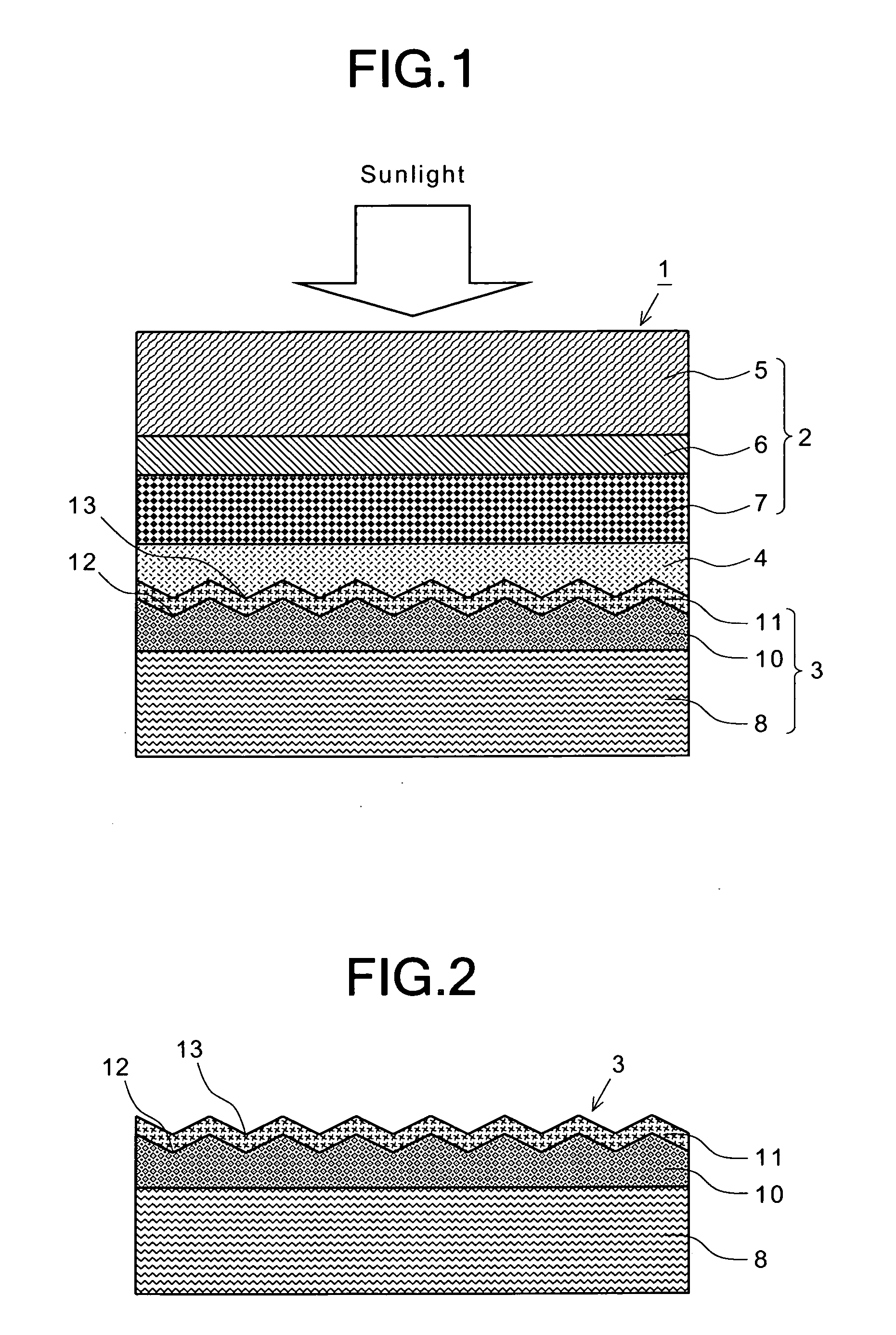
[0015] According to the present invention, the surface of the corrosion-resistant metallic material film formed on the counter substrate has a large number of recesses which are formed in a surface thereof and which are arranged in intervals so that the surface of the corrosion-resistant metallic material film has a waveform cross-section, and the conductive catalytic material film is formed on the surface of the corrosion-resistant metallic material film so as to extend along the surface of the corrosion-resistant metallic material film. Therefore, the contact area of the conductive catalytic material film with the electrolyte increases, so that it is possible to enhance the photoelectric transfer efficiency without increasing the electric resistance even if the thickness of the conductive catalytic material film is decreased. Therefore, according to the present invention, even if an expensive material, such as platinum, is used as the material of the conductive catalytic material film, it is possible to provide an inexpensive counter electrode and an inexpensive dye sensitizing solar cell having the counter electrode since it is possible to decrease the thickness of the conductive catalytic material film.

Problems solved by technology

Originally, dye sensitizing solar cells are not intended for practical use since they have a low photoelectric transfer efficiency.
However, if the thickness of the conductive catalytic material film 111 is decreased, the electric resistance of the counter electrode 103 increases, so that there is a problem in that the photoelectric transfer efficiency deteriorates.

Method used


Image

  • Counter electrode for dye sensitizing solar cell, and dye sensitizing solar cell having same
  • Counter electrode for dye sensitizing solar cell, and dye sensitizing solar cell having same
  • Counter electrode for dye sensitizing solar cell, and dye sensitizing solar cell having same

Examples


Embodiment Construction

[0023] Referring now to the accompanying drawings, the preferred embodiments of the present invention will be described below in detail.

[0024]FIG. 1 shows a preferred embodiment of a dye sensitizing solar cell 1 according to the present invention. As shown in FIG. 1, the dye sensitizing solar cell 1 in this preferred embodiment comprises a photoelectrode 2, a counter electrode 3, and an electrolyte 4 filled in a space therebetween.

[0025] The photoelectrode 2 comprises a transparent substrate member 5 (a light permeable substrate), a transparent electrode film 6 formed on the lower side of the substrate member 5 in FIG. 1, a porous semiconductor electrode film 7 formed on the surface (on the lower side in FIG. 1) of the transparent electrode film 6, and a sensitizing dye absorbed and carried on the porous semiconductor electrode film 7.

[0026] The substrate member 5 may be made of a transparent resin material, such as acrylic resin, polyethylene terephthalate (PET), polyethylene na...


PUM


Abstract

In a counter electrode 3 of a dye sensitizing solar cell 1 wherein an electrolyte 4 is filled in a space between a photoelectrode 2 and the counter electrode 3, a corrosion-resistant metallic material film 10 is formed on a counter substrate 8 so as to have a large number of recesses 13 which are formed in a surface thereof and which are arranged in intervals so that the surface of the corrosion-resistant metallic material film 10 has a waveform cross-section, and a conductive catalytic material film 11 is formed on the surface of the corrosion-resistant metallic material film 10 so as to extend along the surface of the corrosion-resistant metallic material film 10.

Description

BACKGROUND OF THE INVENTION [0001] 1. Field of the Invention [0002] The present invention relates to a counter electrode used as a component of a dye sensitizing solar cell, and a dye sensitizing solar cell having the counter electrode. [0003] 2. Description of the Prior Art [0004] In recent years, from the point of view of environmental issues, solar cells for converting light energy to electric energy have been widely noticed. In particular, dye sensitizing solar cells have been widely noticed since the costs for producing them can be low. Originally, dye sensitizing solar cells are not intended for practical use since they have a low photoelectric transfer efficiency. However, there has been developed a technique using a porous film of particles having a diameter of nanometers as a semiconductor to increase the surface area of an electrode to cause the electrode to absorb a large amount of dye to conspicuously enhance the photoelectric transfer efficiency of a dye sensitizing sol...

Claims


Application Information

Patent Timeline
IPC IPC(8): H01L31/00
CPCH01G9/2022H01G9/2031Y02E10/542
Inventor MIYOSHI, KOZOMIYASAKA, TSUTOMU
Owner ENPLAS CORP
Learn More