
Generator motor device

Inactive Publication Date: 2006-05-18
HONDA MOTOR CO LTD
View PDF7 Cites 12 Cited by
  • Summary
  • Abstract
  • Description
  • Claims
  • Application Information

AI Technical Summary

Benefits of technology

[0007] The present invention has been achieved under the above-mentioned circumstances, and it is an object thereof to cool effectively a motor / generator connected to a displacement type expander as well as improve the efficiency by minimizing escape of heat from the expander.
[0009] In accordance with this arrangement, since the expander casing and the motor / generator casing are joined so as to be hermetically sealed to the outside air, it is possible to prevent the steam from leaking out of the expander casing and the motor / generator casing, and also prevent outside air from contaminating the steam or the oil within the expander casing. Furthermore, since the internal space of the expander casing and the internal space of the motor / generator casing are made to communicate with each other via the through hole, not only is it possible to cool the motor / generator, which has a high temperature as a result of functioning as a generator or a motor, with low temperature steam that has leaked out of a working chamber of the expander to the interior of the expander casing and flowed into the interior of the motor / generator casing via the through hole, but it is also possible to minimize the escape of heat from the expander casing and thus improve the efficiency of the expander as a result of the high temperature motor / generator casing and the low temperature expander casing being joined. In particular, since the expander is of a displacement type, the steam that has leaked out of the expansion chamber has relatively low temperature and pressure, thereby enabling the motor / generator to be cooled effectively.
[0011] In accordance with this arrangement, since the upper parts of the internal spaces of the expander casing and the motor / generator casing are made to communicate with each other via the through hole, it is possible to introduce steam alone into the motor / generator casing while preventing the oil within the expander casing from entering the motor / generator casing.
[0013] In accordance with this arrangement, since the liquid return passage is provided in the lower parts of the expander casing and the motor / generator casing, it is possible to return the water and oil that have accumulated within the motor / generator casing to the expander casing, thereby preventing any degradation in durability of the motor / generator.
[0015] In accordance with this arrangement, since the motor casing is detachably joined to the expander casing, the ease of maintenance of the expander and the motor / generator is improved, and since the motor / generator casing covers the output shaft support provided on the expander casing, it is possible to efficiently transmit heat of the motor / generator to the expander.
[0017] In accordance with this arrangement, since it is possible for the rotor of the motor / generator fixed to the shaft end of the output shaft of the expander to have a depression as a result of the permanent magnet being supported on the surface of the rotor, and the bearing for cantilever support of the shaft end of the output shaft on the expander casing is housed within the depression, it is unnecessary to provide on the motor / generator casing a bearing for supporting the output shaft, and as a result it is possible to decrease the number of components and reduce the axial dimensions of the motor / generator. Furthermore, because of the elimination of the bearing, it is unnecessary to store oil within the expander casing, thereby preventing any degradation in durability of the motor / generator due to the oil.

Problems solved by technology

The arrangement disclosed in Japanese Patent Application Laid-open No. 5-98902 carries out cooling by employing a can type generator and putting the stator coil in direct contact with the atmosphere, but it is difficult for this alone to achieve a sufficient cooling effect.
However, unlike working medium discharged from a displacement type expander, the working medium discharged from the non-displacement type expander has high temperature and high pressure, and cannot realistically be expected to have an effect in cooling the generator.

Method used


Image

  • Generator motor device
  • Generator motor device
  • Generator motor device

Examples


Embodiment Construction

[0035] A mode for carrying out the present invention is explained below with reference to an embodiment of the present invention shown in the attached drawings.

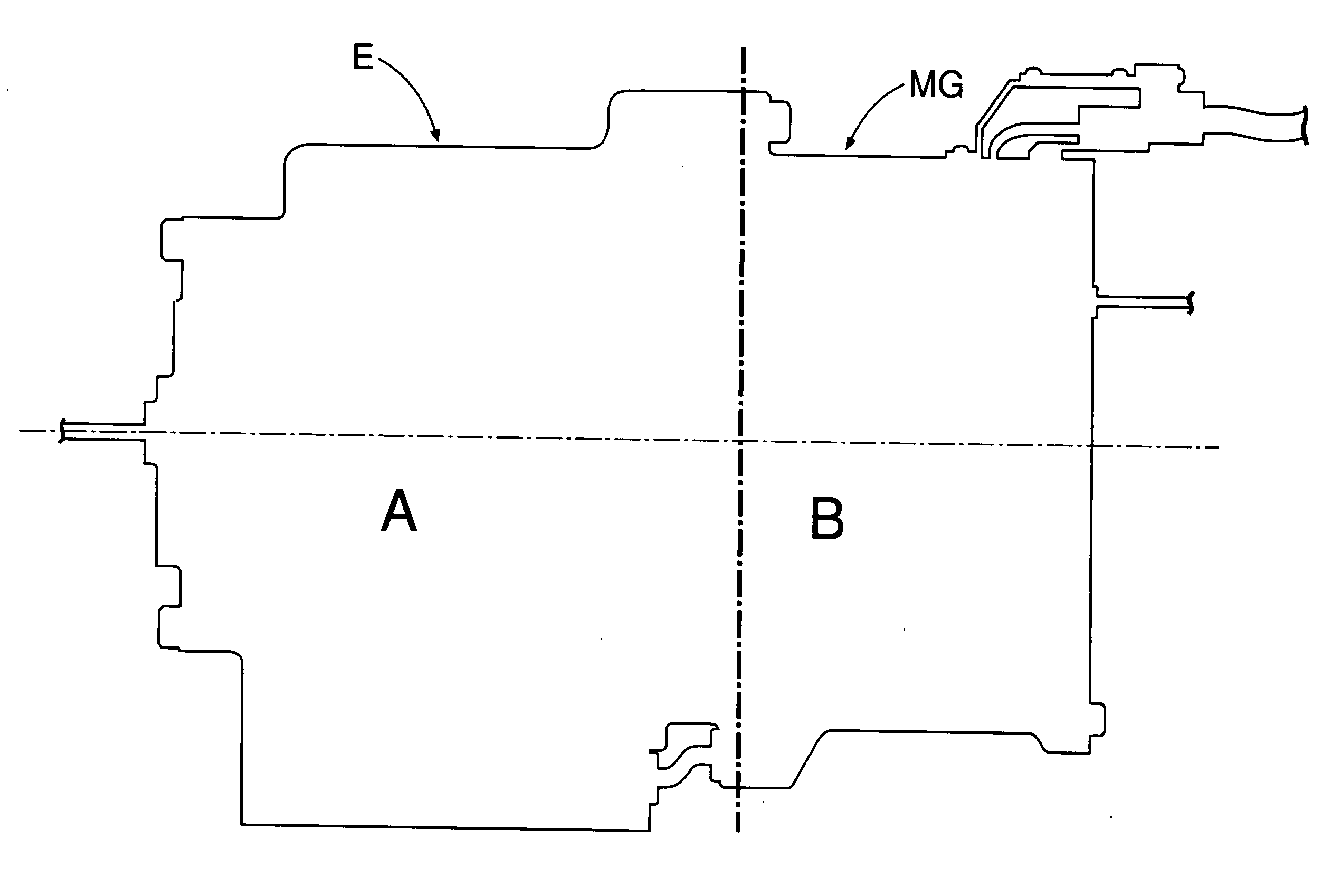
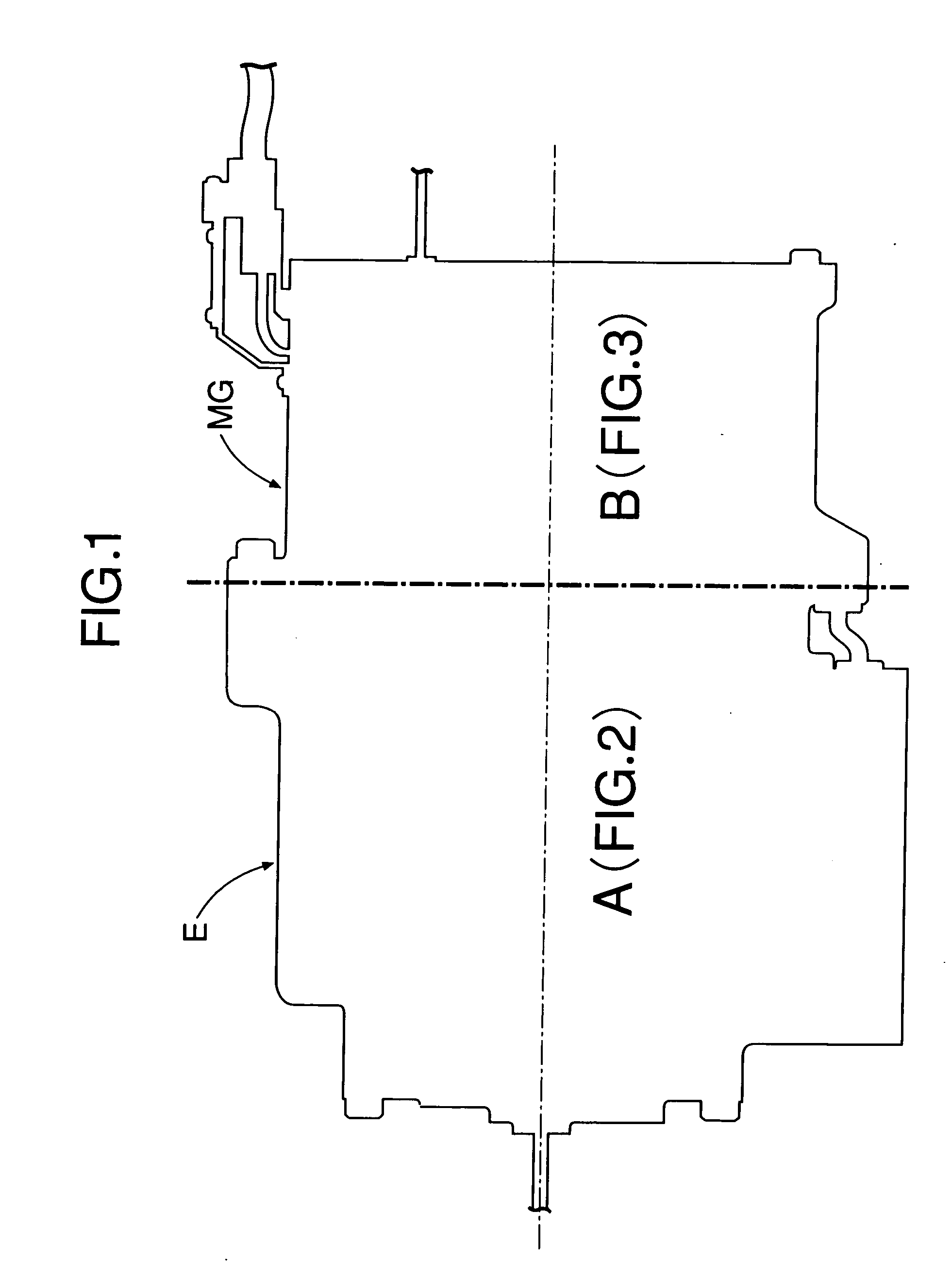
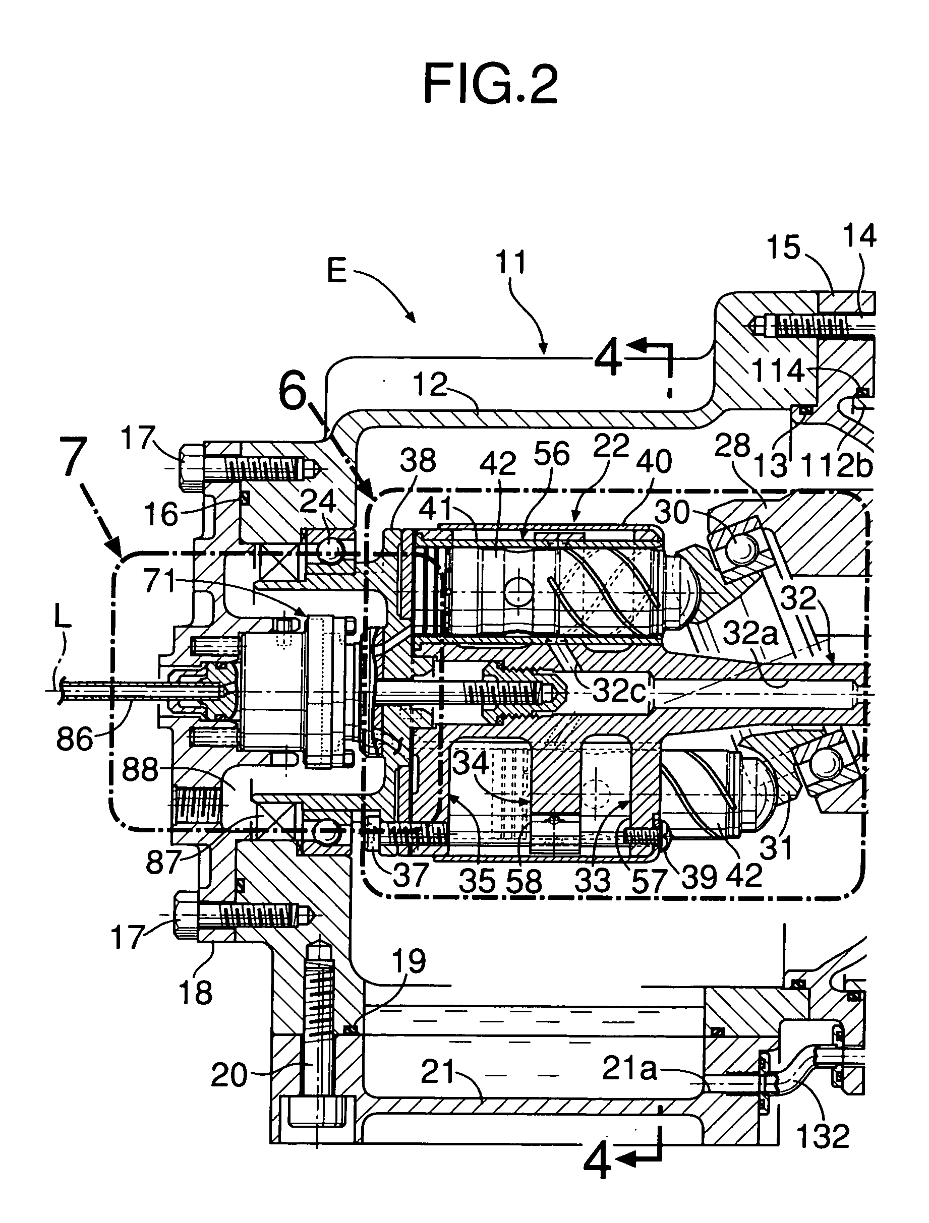
[0036]FIG. 1 to FIG. 15 show one embodiment of the present invention.

[0037] As shown in FIG. 1 to FIG. 11, an expander E of this embodiment is used in, for example, a Rankine cycle system, and outputs mechanical work by adiabatic expansion of high temperature, high pressure steam as a working medium. A casing 11 of the expander E is formed from a casing main body 12, a front cover 15 joined via a seal 13 to a front opening of the casing main body 12 by a plurality of bolts 14, a rear cover 18 joined via a seal 16 to a rear opening of the casing main body 12 by a plurality of bolts 17, an oil pan 21 joined via a seal 19 to a lower opening of the casing main body 12 by a plurality of bolts 20, a pump housing 102 joined to a front face of the front cover 15 by a plurality of bolts 101, and a pump cover 104 joined to a front fa...


PUM


Abstract

A motor / generator system is provided in which a casing (111) of a motor / generator (MG) is connected to a casing (15) of a displacement type expander of a Rankine cycle system, and a rotor (117) of the motor / generator (MG) is supported on a shaft end of an output shaft (32) extending from the expander to the interior of the motor / generator casing (111). Providing communication between an internal space of the expander casing (15), where steam that has leaked from an expansion chamber of the expander is present, and an internal space of the motor / generator casing (111) via a through hole (15a) enables the motor / generator (MG), which reaches a high temperature due to generation of heat in a coil (124), to be cooled by leaked steam that has entered via the through hole (15a), and covering the low temperature expander casing (15) with the high temperature motor / generator casing (111) enables the escape of heat from the expander casing (15) to be minimized, thereby enhancing the efficiency of the expander. It is thus possible to cool effectively the motor / generator connected to the displacement type expander and at the same time minimize the escape of heat from the expander, thereby enhancing the efficiency.

Description

FIELD OF THE INVENTION [0001] The present invention relates to a motor / generator system in which a motor / generator is connected to an output shaft of a displacement type expander that converts adiabatic expansion of high temperature, high pressure steam into mechanical work. BACKGROUND ART [0002] Japanese Patent Application Laid-open No. 5-98902 discloses an arrangement in which a casing of a displacement type expander of a Rankine cycle system is integrated with a casing of a motor driven by an output shaft of the expander so as to have a structure that is hermetically sealed to the atmosphere, thus preventing leakage of ammonia or Freon, which are working media, from the casing of the expander or the casing of the generator to the atmosphere. The motor is of a so-called can type, the outer periphery of a rotor being covered by a can forming a part of the casing of the motor so as to isolate the rotor from a stator, thus preventing the working medium from leaking past the stator, p...

Claims


Application Information

Patent Timeline
IPC IPC(8): F04B35/00F04B27/08F04B17/00F04B47/08F04B1/12F01B31/26H02K5/20H02K5/10H02K5/173H02K7/14H02K7/18H02K9/00H02K9/02H02K9/12
CPCH02K7/14H02K7/1823
Inventor FUKUTOMI, KOJIMAKINO, HIROYUKIMAEDA, SUSUMU
Owner HONDA MOTOR CO LTD
Learn More