
Management interface for a system that provides automated, real-time, continuous data protection

a management interface and data protection technology, applied in the field of enterprise data protection, can solve the problems of staggering costs, data loss, data recovery, and the cost of “code red” virus alone, and achieve the effects of reducing the number of downtime, data loss, and recovery

Active Publication Date: 2006-05-11
QUEST SOFTWARE INC
View PDF99 Cites 169 Cited by
  • Summary
  • Abstract
  • Description
  • Claims
  • Application Information

AI Technical Summary

Benefits of technology

[0017] The time control enables the management interface to operate within a history mode in which the display provides a visual representation of a “virtual” point in time in the past during which the data management system has been operative to provide the data protection service. In addition, the management interface can be toggled to operate in a real-time mode, which provides an active view of the most current protected data as it changes in real-time, typically driven by changes to primary storage. This real-time mode provides the user with the ability to view changes that occur to a set of data currently visible on the display screen. As an example, if the interface is displaying the contents of directory D1, and a file F1 in the directory is created on primary storage, then file F1 automatically appears in the display in the appropriate position in the data hierarchy.

Problems solved by technology

A critical information technology (IT) problem is how to cost-effectively deliver network wide data protection and rapid data recovery.
The “code red” virus alone cost an estimated $2.8 B in downtime, data loss, and recovery.
The reason for these staggering costs is simple—traditional schedule based tape and in-storage data protection and recovery approaches can no longer keep pace with rapid data growth, geographically distributed operations, and the real time requirements of 24×7×265 enterprise data centers.
Yet, without data availability, applications cannot be available.
The overhead and data management maze that existing approaches bring to the network, storage, tape, and application infrastructure has caused increasing expenditures with little tangible returns for the enterprise.
Worse, manual recovery techniques compound the problem with the same issues that cause downtime in the first place—human errors and process issues constitute 80% of unplanned downtime.
As a result, businesses are enduring high costs, high risk, and a constant drag on productivity.

Method used


Image

  • Management interface for a system that provides automated, real-time, continuous data protection
  • Management interface for a system that provides automated, real-time, continuous data protection
  • Management interface for a system that provides automated, real-time, continuous data protection

Examples


Embodiment Construction

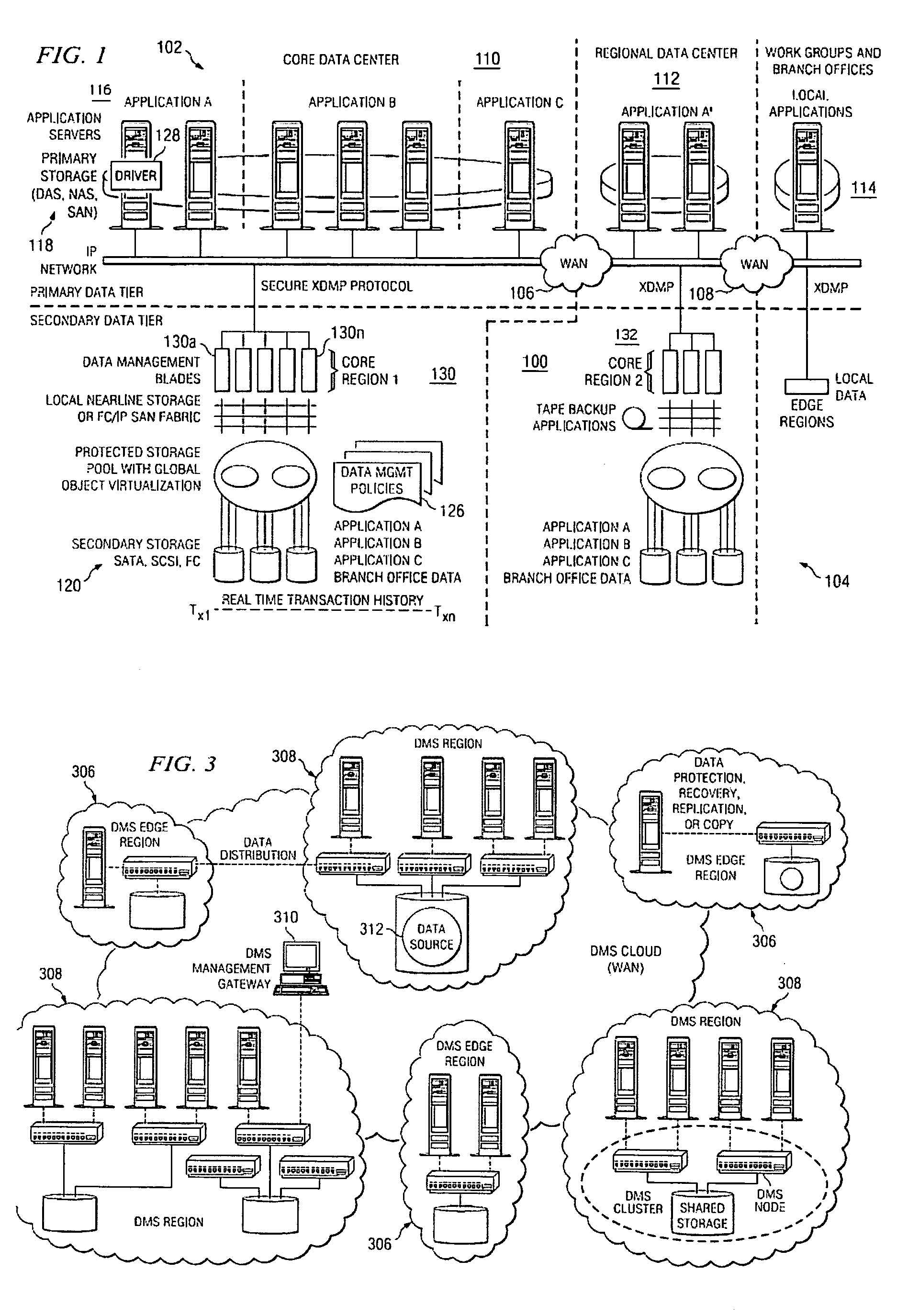
[0042] As illustrated in FIG. 1, the present invention is now described in the context of a data management system (DMS) that is implemented as a network (a wide area network “cloud”) of peer-to-peer DMS service nodes. The invention is not limited to use with such a system, however.

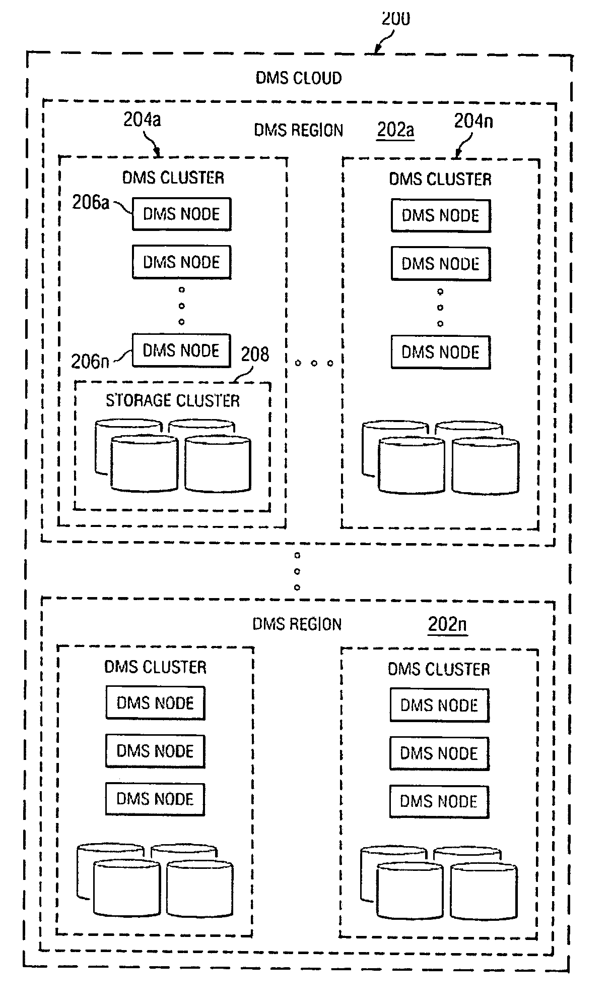
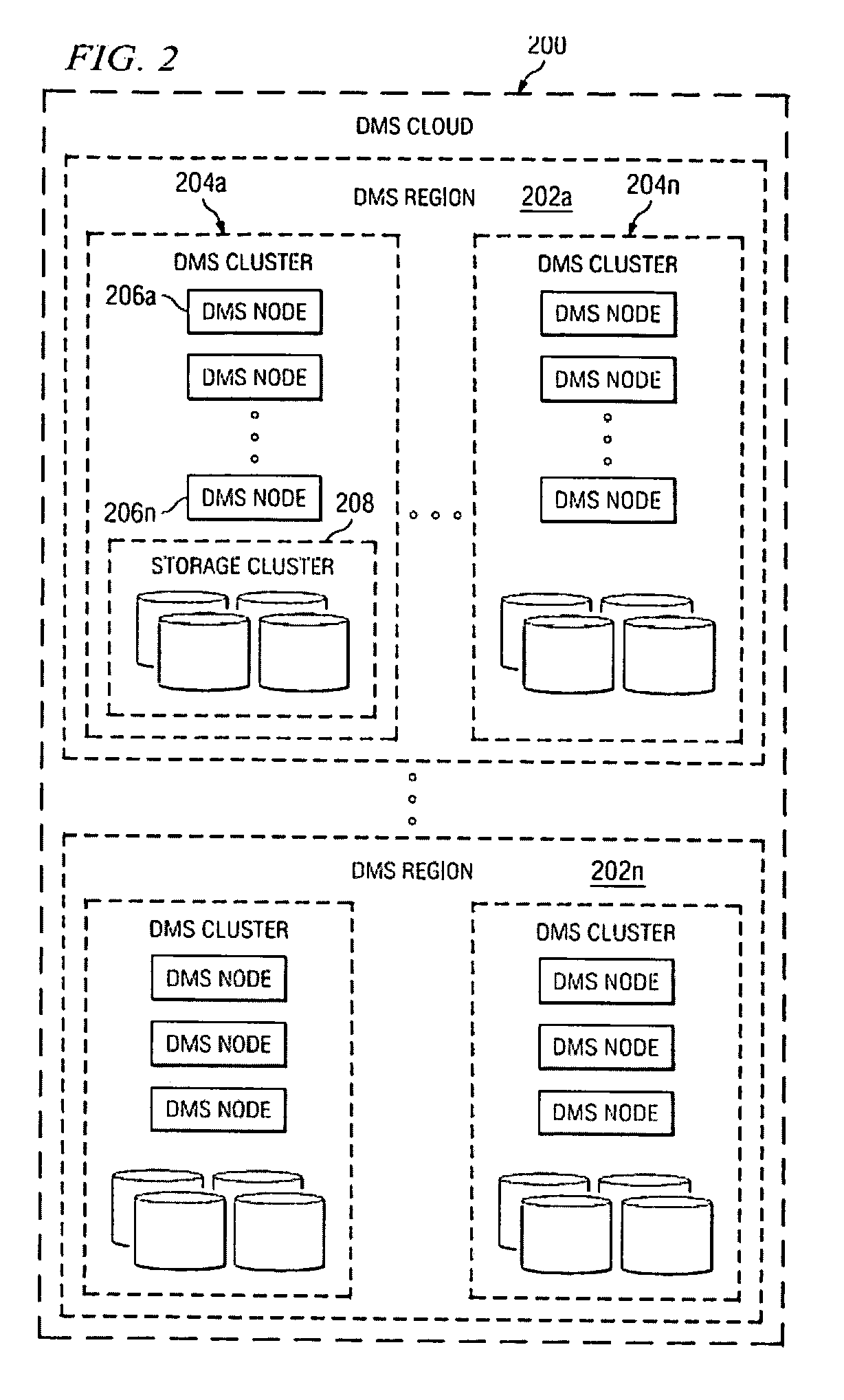
[0043] By way of brief background, FIG. 2 illustrates a hierarchical structure of a data management system 200 in which the invention may be implemented. As illustrated, the data management system 200 comprises one or more regions 202a-n, with each region 202 comprising one or more clusters 204a-n. A given cluster 204 includes one or more nodes 206a-n and a shared storage 208 shared by the nodes 206 within the cluster 204. A given node 206 is a data management server as described above with respect to FIG. 1. Within a DMS cluster 204, preferably all the nodes 206 perform parallel access to the data in the shared storage 208. Preferably, the nodes 206 are hot swappable to enable new nodes to be added and ...


PUM


Abstract

A data management system that protects data into a continuous object store includes a management interface having a time control. The time control allows an administrator to specify a “past” time, such as a single point or range. When the time control is set to a single point, a hierarchical display of data appears on a display exactly as the data existed in the system at that moment in the past. Preferably, the visualization includes both the structure of the hierarchy (e.g., the identity of the directories, their files, databases, and the like) and also the contents of the data objects themselves (i.e., what was in the files and databases). The time control enables the management interface to operate within a history mode in which the display provides a visual representation of a “virtual” point in time in the past during which the data management system has been operative to provide the data protection service. In addition, the management interface can be toggled to operate in a real-time mode, which provides an active view of the system data as it changes in real-time, typically driven by changes to primary storage. This real-time mode provides the user with the ability to view changes that occur to a set of data currently visible on the display screen. The interface also allows an administrator to specify and manage policy including, without limitation, how long data is retained in the management system. A policy engine enables the user to assert “temporal-based” policy over data objects.

Description

[0001] This application is based on and claims priority to provisional application Ser. No. 60 / 624,358, filed Nov. 2, 2005. CROSS-REFERENCE TO RELATED APPLICATIONS [0002] This application also is related to commonly-owned applications: [0003] Ser. No. 10 / 841,398, filed May 7, 2004, and titled “METHOD AND SYSTEM FOR AUTOMATED, NO DOWNTIME, REAL-TIME, CONTINUOUS DATA PROTECTION.”[0004] Ser. No. 11 / 123,994, filed May 5, 2005, and titled “SYSTEM FOR MOVING REAL-TIME DATA EVENTS ACROSS A PLURALITY OF DEVICES IN A NETWORK FOR SIMULTANEOUS DATA PROTECTION, REPLICATION, AND ACCESS SERVICES.”BACKGROUND OF THE INVENTION [0005] 1. Technical Field [0006] The present invention relates generally to enterprise data protection. [0007] 2. Background of the Related Art [0008] A critical information technology (IT) problem is how to cost-effectively deliver network wide data protection and rapid data recovery. In 2002, for example, companies spent an estimated $50 B worldwide managing data backup / rest...

Claims


Application Information

Patent Timeline
IPC IPC(8): G06F9/44
CPCG06F11/1458G06F11/1461G06F11/1448G06F17/3023G06F11/1464G06F17/30126G06F11/1456G06F16/168G06F16/1873
Inventor SIM-TANG, SIEW YONGFRAISL, DANIEL J.HOEBER, ANTHONY N.
Owner QUEST SOFTWARE INC
Learn More