
System and method for vibration monitoring

Active Publication Date: 2006-05-11
ABB (SCHWEIZ) AG
View PDF22 Cites 38 Cited by
  • Summary
  • Abstract
  • Description
  • Claims
  • Application Information

AI Technical Summary

Benefits of technology

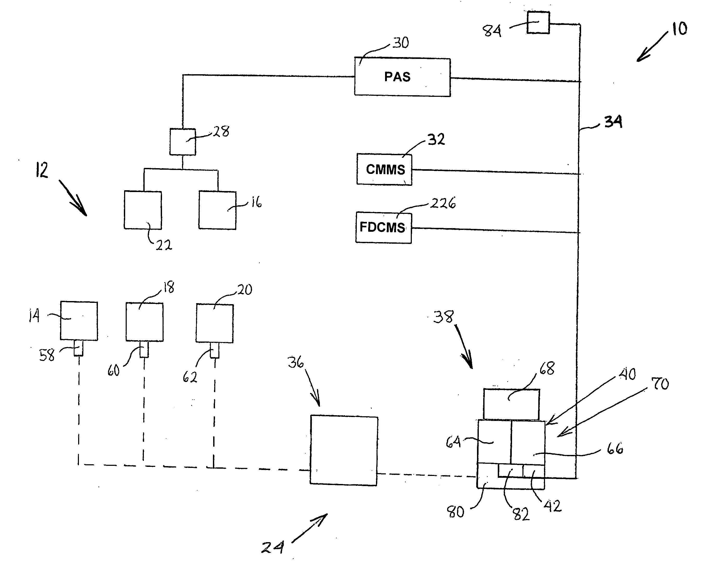
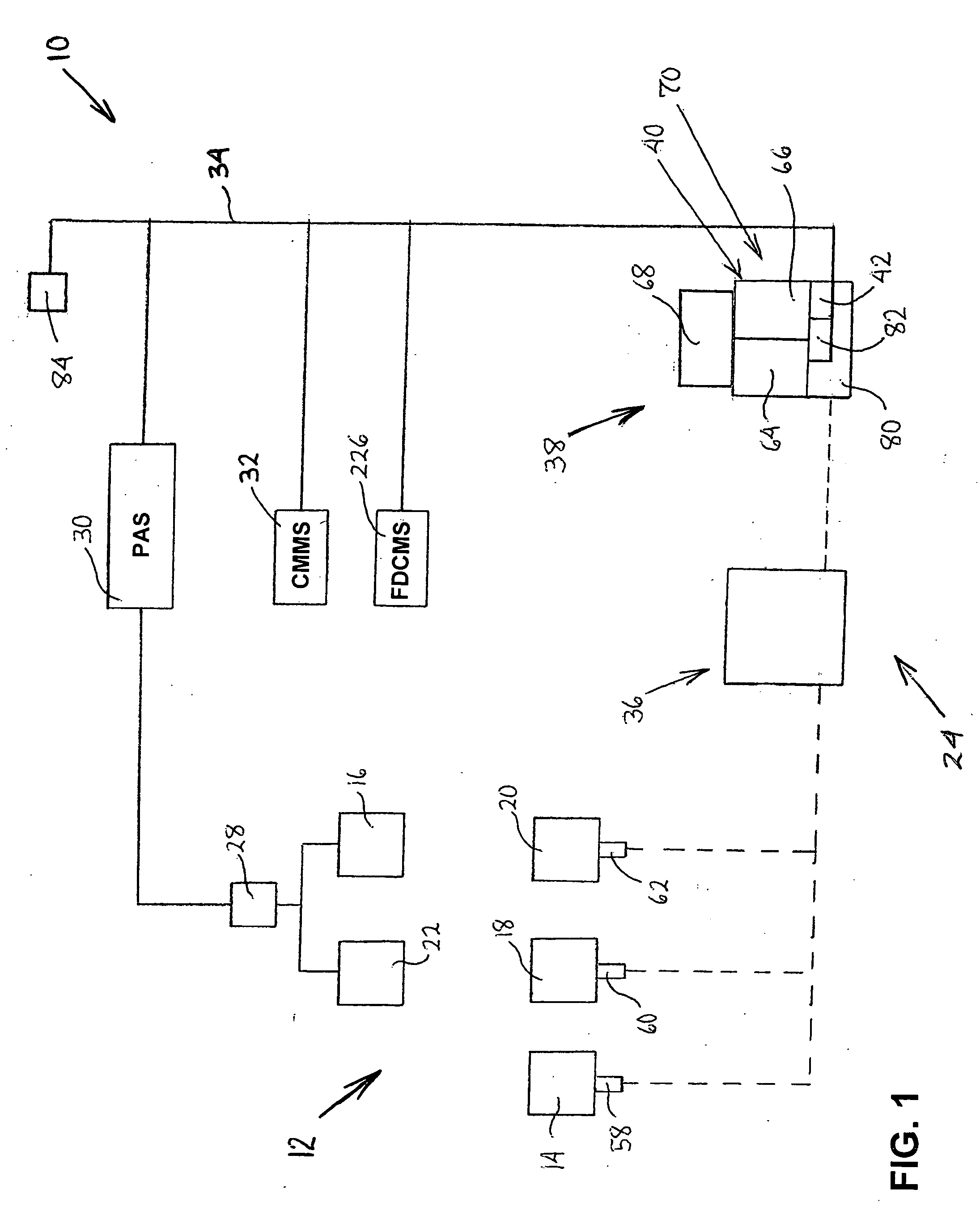
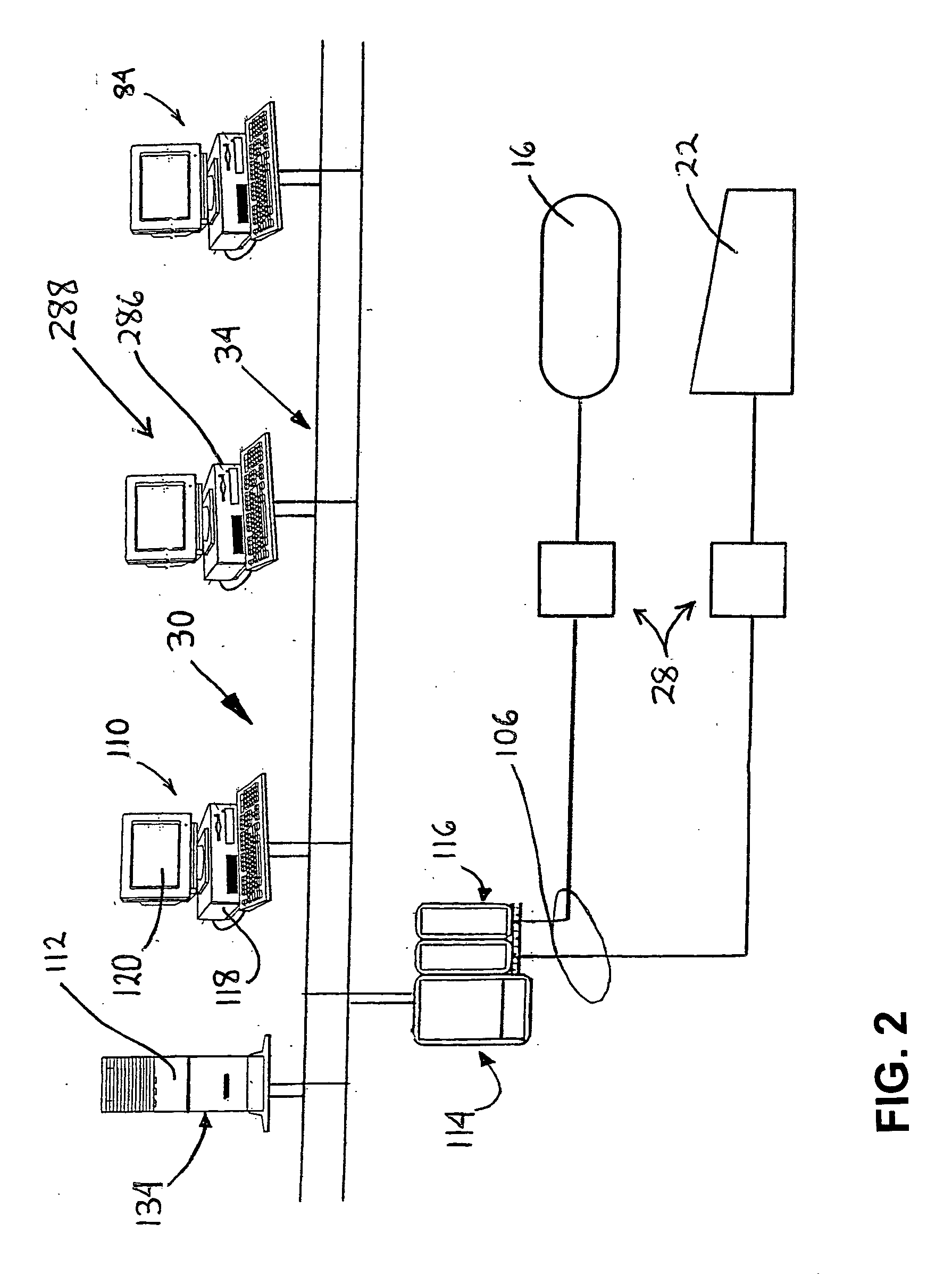
[0006] In accordance with the present invention, a system is provided for use in controlling a process of an enterprise and for providing a condition diagnosis of a machine in the enterprise based on vibration data collected from the machine. The system includes at least one computer and a monitor connected to the at least one computer. A diagnostic software system runs on the at least one computer and is operable to provide the condition diagnosis of the machine based on the collected vibration data. A human system interface (HSI) runs on the at least one computer and is communicably connected to the diagnostic softw

Problems solved by technology

Thus, in a plant that utilizes a vibration monitoring system, along with a process automation system and a computerized maintenance management system (CMMS), the vibration monitoring system typically does not communicate with the process automation system or the CMMS.
As a result, an operator at a workstation of the process automation system cannot access detailed information from the vibration monitoring system.

Method used


Image

  • System and method for vibration monitoring
  • System and method for vibration monitoring
  • System and method for vibration monitoring

Examples


Embodiment Construction

[0025] It should be noted that in the detailed description that follows, identical components have the same reference numerals, regardless of whether they are shown in different embodiments of the present invention. It should also be noted that in order to clearly and concisely disclose the present invention, the drawings may not necessarily be to scale and certain features of the invention may be shown in somewhat schematic form.

[0026] Below is a list of acronyms used in the specification and their respective meanings: [0027]“CMMS” shall mean computerized maintenance management system [0028]“DCOM” shall mean distributed component object model. [0029]“DLL” shall mean dynamic link library. [0030]“FDCMS” shall mean field device calibration and management system [0031]“HTML” shall mean Hypertext Markup Language. [0032]“HTTP” shall mean Hypertext Transfer Protocol. [0033]“ODBC” shall mean Open Data Base Connectivity, which is a method of communication to client / server databases. ODBC i...


PUM


Abstract

The present invention is directed to a system and method of monitoring assets of an enterprise, wherein the assets perform a process and include machines subject to vibration. The system includes a vibration diagnostic software system integrated with a process automation system and a computerized maintenance management system to provide a single window interface for controlling and monitoring a process, for monitoring and analyzing the vibration of the machines associated with the process and for managing the maintenance of the machines. This integration brings vibration data collection, transmission, analysis, historical recording, display and maintenance activities all together in a defined workflow.

Description

BACKGROUND OF THE INVENTION [0001] The present invention is directed toward vibration monitoring and, more particularly, toward a system and method for monitoring the vibration of machinery from the same point that other assets may be monitored or controlled from. [0002] An operating machine, such as a pump or a fan, has a normal or baseline vibration pattern or signature that is characteristic of normal operation of the machine. If the machine is not operating normally, the machine will typically have a vibration signature that differs from the baseline vibration signature. Typically, this difference in vibration signature is unique to the problem with the machine, i.e., the problem causes a telltale change in the vibration signature. Thus, vibration analysis of a machine can detect developing mechanical defects long before they become a threat to the integrity of the machine, thereby providing the necessary lead-time to schedule maintenance to suit the needs of enterprise manageme...

Claims


Application Information

Patent Timeline
IPC IPC(8): G06F11/30
CPCG01H1/00G05B23/0267G05B23/0216
Inventor POORMAN, ANNEGRAMBERG, OLIVERSTEEN, CHEN YANG
Owner ABB (SCHWEIZ) AG
Learn More