
Energy self-supply type controllable stopping device

A parking device and energy technology, applied in track brakes, railway car body parts, vehicle route interaction equipment, etc., can solve the problems of difficult speed measurement, high cost, serious oil leakage, etc., and achieve easy daily maintenance management, saving engineering investment, Good sealing performance

Inactive Publication Date: 2006-10-04
沈阳中铁安全设备有限责任公司
View PDF0 Cites 12 Cited by
  • Summary
  • Abstract
  • Description
  • Claims
  • Application Information

AI Technical Summary

Problems solved by technology

[0002] At present, the speed control equipment used in the railway marshalling yard for the speed control or brake parking of rolling vehicles requires energy except the deceleration top. Some directly use electric drive, and some use air pressure system or hydraulic system. , accumulators, oil pumps or air pumps, all need to connect pipelines and joints, need large-capacity transformers and lay power cables, etc., consume a lot of electric energy, the amount of work is large, the cost is high, and maintenance is difficult
Especially in recent years, the hydraulic controllable parking devices used in China have too many joints, serious oil leakage, large power consumption, difficult maintenance, and some cannot be used normally.
As a device for the purpose of braking protection, there are also disadvantages such as difficulty in speed measurement and the need to manually restore the brake once overspeed occurs.

Method used


Image

  • Energy self-supply type controllable stopping device
  • Energy self-supply type controllable stopping device
  • Energy self-supply type controllable stopping device

Examples


Embodiment Construction

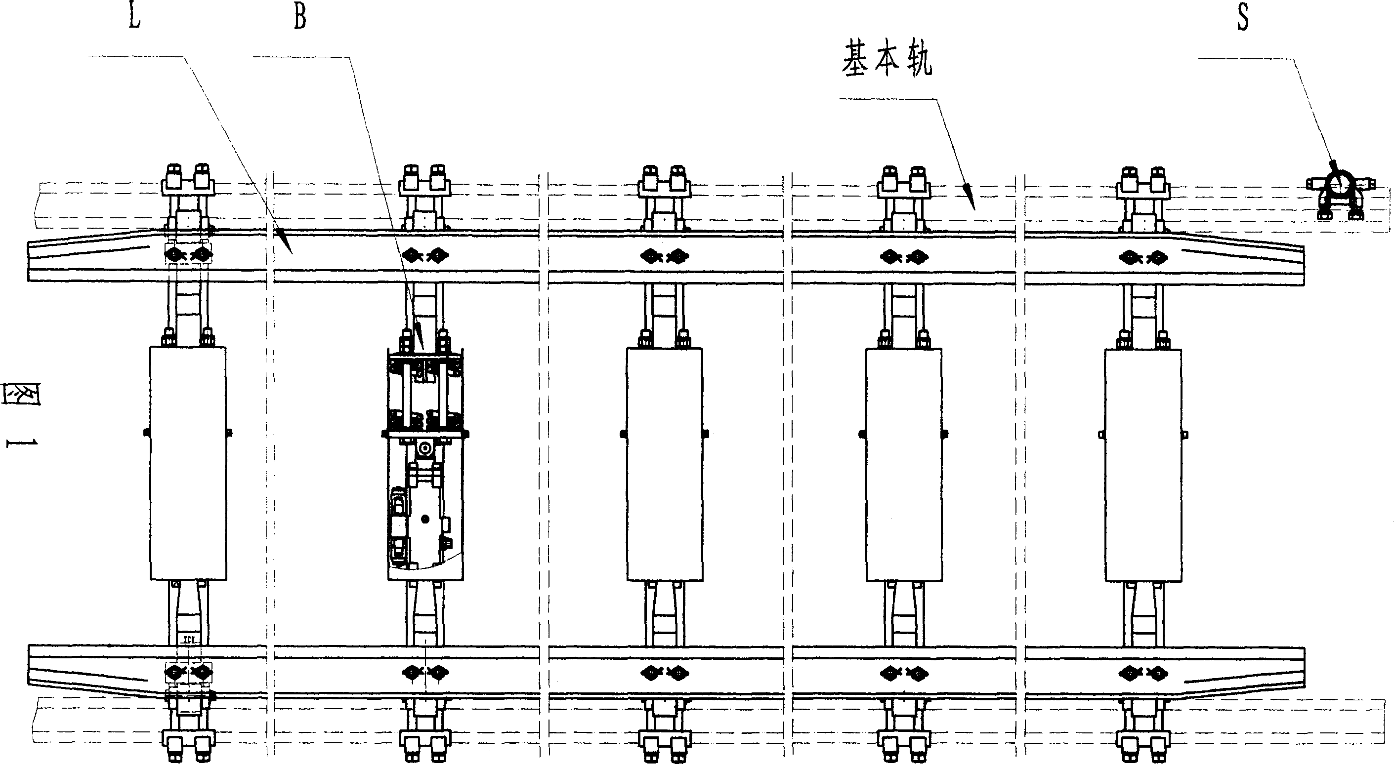
[0051] As shown in Figure 1, the self-energy controllable parking device is composed of a speed judgment top S, a support arm B and a brake beam L. The speed judgment top S is set in front of the self-energy controllable parking device, that is, the entrance of the vehicle, and is fastened and installed on the outside of the basic rail of the line with bolts B1 and nuts B2; The card 17 is clamped on the bottom of the basic rail, and fastened with bolts B1 and nuts B2; the brake beam L is fastened with bolts B1, nuts B2, etc. Above the bolster.

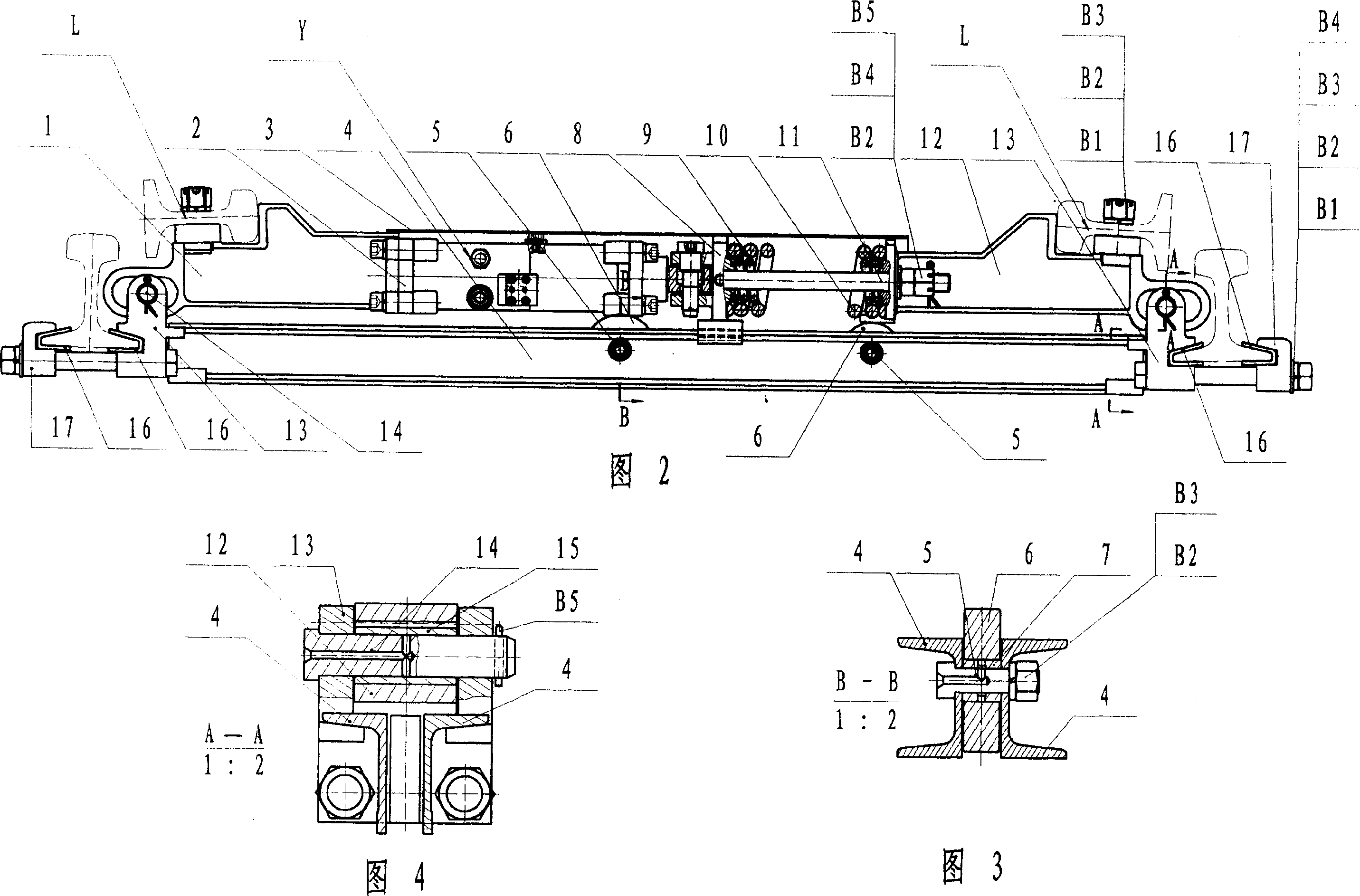
[0052] Figure 2, Figure 3, Figure 4, Figure 5 As shown, the support arm B consists of a left support arm 1, a spacer 2, a protective cover 3, a joist 4, a hydraulic device Y, a support wheel shaft 5, a support wheel 6, a support wheel sleeve 7, a spring seat 8, an inner spring 9, Outer spring 10, screw rod 11, right support arm 12, inner rail clip 13, support arm shaft 14, support arm bushing 15, insulating groove 16, outer rail clip...


PUM


Abstract

The invention discloses a self energy resource controlled parking equipment,which comprises the following parts: decision rapid roof, support arm and brake beam, wherein the decision rapid roof is installed at the entrance end of parking car in front of the parking equipment; the spiro is at the outside of circuit stock rail; the support arm uses the inside and outside rail anchor to fix on the stock rail bottom and uses the bolt to fix; the brake beam snail is fixed on the support bolster; the hydraulic press is a closed hydraulic system which is integrated with hydraulic cylinder, plunger piston, reversing solenoid valve, one-way valve, accumulator, which can saves the generator, air pump, lubricant pump,accumulator,power cable,conduit line,adaptor and other external devices; when the parking equipment installs at the bottom of the classification track is use for as parking equipment, the normal condition is application position; the order is controlled by controlling building; the proof slide vehicle is carried out the automatic stopping which installs target section behind the goal application position exit; when parking equipment is used for goal brake, the normal condition is for alleviation position to carry out braking speed governing. The invention simplifies the structure, which uses widely.

Description

technical field [0001] The invention relates to a self-energy controllable parking device for a railway marshalling yard to adjust the speed or brake a vehicle for parking, and belongs to the technical field of railway marshalling yard speed regulation. Background technique [0002] At present, the speed control equipment used in the railway marshalling yard for the speed control or brake parking of rolling vehicles requires energy except the deceleration top. Some directly use electric drive, and some use air pressure system or hydraulic system. , accumulators, oil pumps or air pumps all need to connect pipelines and joints, need large-capacity transformers and lay power cables, etc., consume a lot of electric energy, have a large amount of engineering, high costs, and difficult maintenance. Especially in recent years, the hydraulic controllable parking devices used in China have too many joints, serious oil leakage, large power consumption, difficult maintenance, and some ...

Claims


Application Information

Patent Timeline
Patent Type & Authority Applications(China)
IPC IPC(8): B61K7/06B61L1/00
Inventor 杨恩久
Owner 沈阳中铁安全设备有限责任公司
Learn More