
Apparatus and method for monitoring optical signal-to-noise ratio

a technology of optical signal and signal to noise ratio, which is applied in the field of apparatus and a method for monitoring optical signal tonoise ratio (osnr), can solve the problems of deterioration of osnr, significant reduction of transmission efficiency of optical communication system, and amplification of noise accompanied with optical signal, so as to improve the detection sensitivity and dynamic range of two photodiodes, maintain noise power measurement accuracy, and improve the effect of osnr monitoring quality

Inactive Publication Date: 2006-05-11
IND TECH RES INST
View PDF8 Cites 20 Cited by
  • Summary
  • Abstract
  • Description
  • Claims
  • Application Information

AI Technical Summary

Benefits of technology

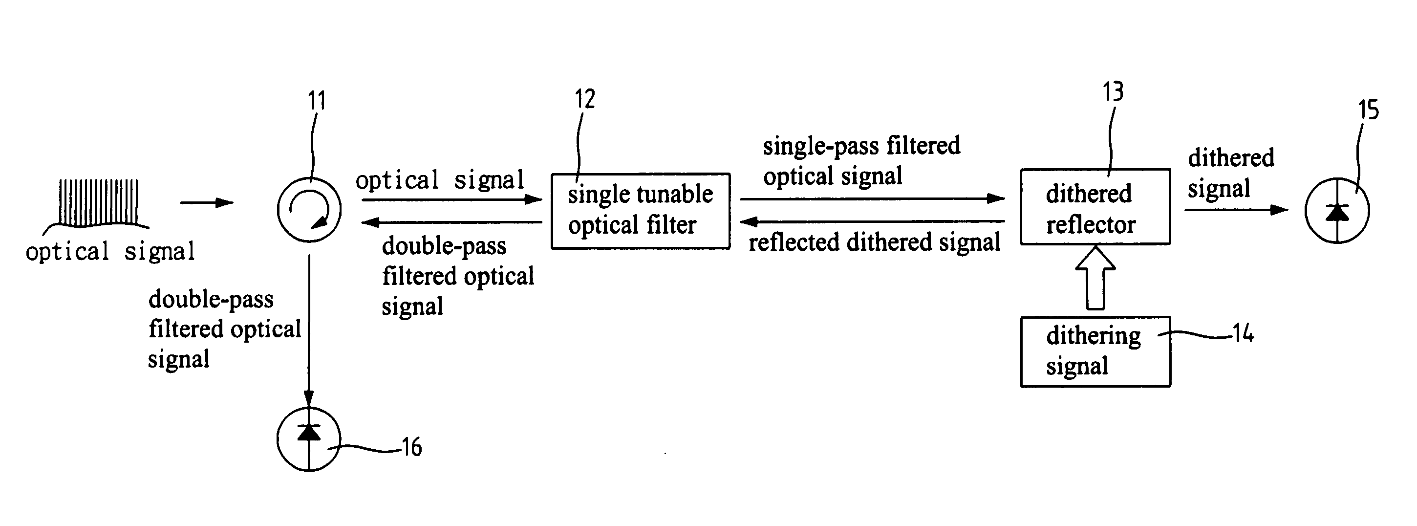
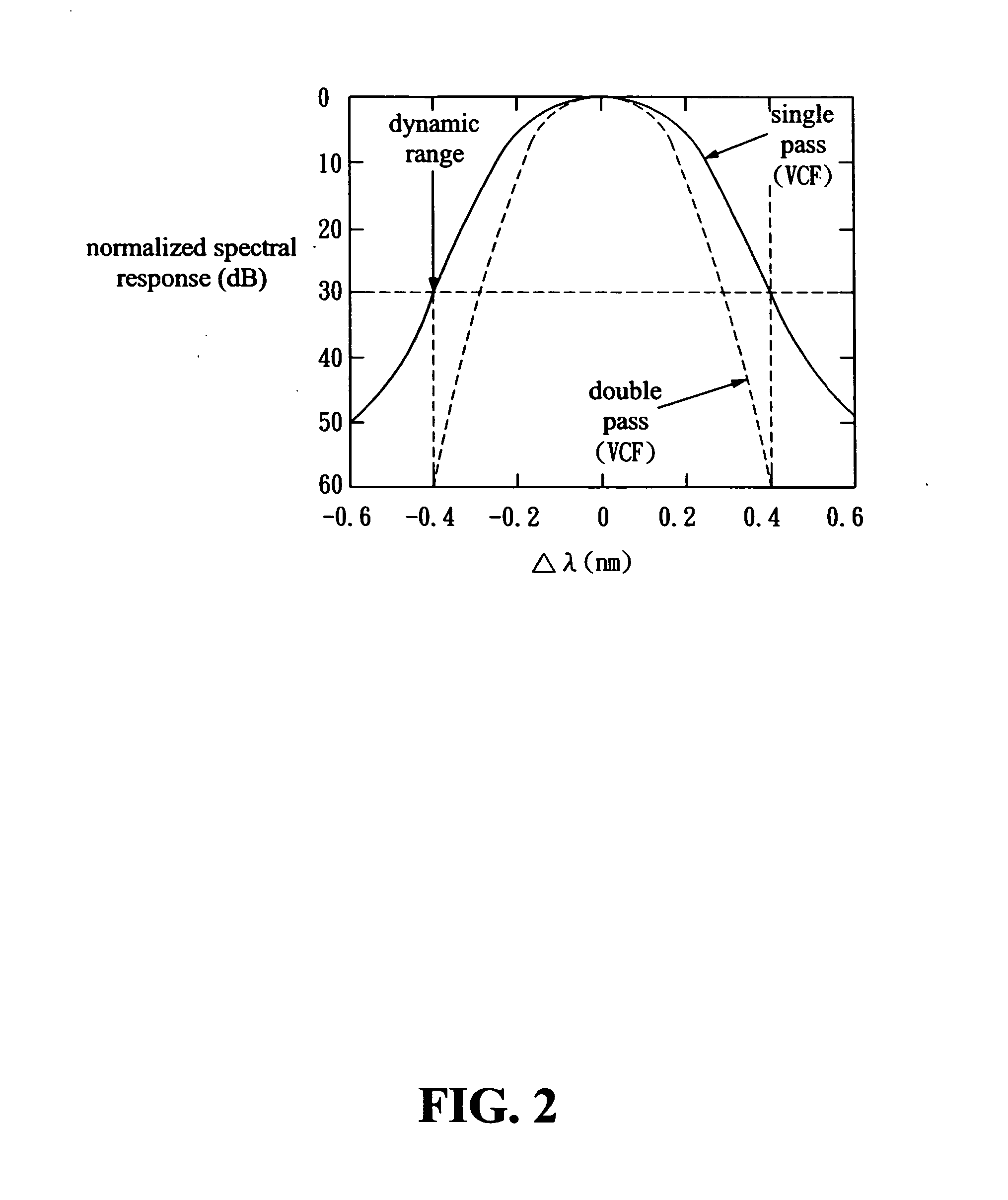
[0009] The present invention provides a technique that uses the reflection function of a dithered reflector to pass the optical signal through a TOF once and the noise through the TOF twice. The dithering function of the dithered reflector can increase the detection sensitivity and dynamic range of the two photodiodes. When the TOF is scanning and filtering the whole optical spectrum, the optical signal power and the noise power are simultaneously measured by the two photodiodes, respectively. The OSNR value of each optical channel is then calculated based on the measured data.
[0010] Moreover, the present invention adopts a dithering technique that imposes a dithering signal on the dithered reflector. The reflected dithered noise can be clearly separated from the residual reflected signal and the signal leaked from the optical circulator. Consequently, the accuracy of noise power measurement is maintained and high quality of OSNR monitoring is achieved.

Problems solved by technology

An amplified spontaneous emission (ASE) noise, which is first produced by an optical amplifier and then received by a receiver, may result in a significant reduction of the transmission efficiency of an optical communication system.
However, the noise accompanied with the optical signal is amplified as well.
The end result is a deterioration of the OSNR.
For most optical filtering approaches, it is generally difficult to use a single tunable optical filter (TOF) for both optical signal power and noise power measurements.
Its drawback is an increase of the complexity due to the use of a dual sweep and the requirements of a wide RBW optical filter and a narrow RBW optical filter.
Besides, it occupies more space than that required for other techniques.
Therefore, its requirements of wavelength monitoring are not very strict.
The conventional techniques mentioned above for monitoring OSNR, a dual sweep technique and a double-pass filtering technique applied to OSAs, will result in an increase of both complexity and cost.

Method used


Image

  • Apparatus and method for monitoring optical signal-to-noise ratio
  • Apparatus and method for monitoring optical signal-to-noise ratio
  • Apparatus and method for monitoring optical signal-to-noise ratio

Examples


Embodiment Construction

[0026] The present invention improves the method of OSNR measurement proposed by Chappell. In Chappell's method, two different filters are used alternately. One filter with a wide enough RBW to accommodate the signal spectrum is adopted for measuring optical signal power. Another filter with a narrow enough RBW to reject adjacent optical channels is adopted for measuring noise power.

[0027]FIG. 1 is a block diagram of an OSNR monitoring apparatus according to the present invention. Referring to FIG. 1, the OSNR monitoring apparatus of the present invention comprises an optical circulator 11, a TOF 12, a dithering signal 14, a dithered reflector 13, and two photodiodes 15 and 16. The optical circulator 11 has a circular transmission function, which guides input signals from a communication system to a specified output trajectory. The TOF 12 has a bidirectional filtering function, which receives a signal (for example, DWDM signal) from optical circulator 11 and outputs a single-pass f...


PUM


Abstract

An apparatus and a method for monitoring optical signal-to-noise ratio are provided. It can be applied in dense wavelength-division multiplexed networks to monitor the transmission quality of each optical channel. The apparatus comprises an optical circulator, a tunable optical filter, a dithering signal, a dithered reflector, and two photodiodes. It can be integrated on a single chip. The invention utilizes the dithering and reflection functions of the dithered reflector, and passes the signal and the noise through the tunable optical filter once and twice, respectively. When the tunable optical filter is scanning and filtering the whole spectrum, the signal and noise powers are measured by the two photodiodes, respectively. The OSNR for each optical channel is then calculated according to the signal and noise powers. It can monitor channel location, wavelength drift, and OSNR by including a wavelength locker to act as an optical channel analyzer.

Description

FIELD OF THE INVENTION [0001] The present invention generally relates to an apparatus and a method for monitoring optical signal-to-noise ratio (OSNR), which can be applied in dense wavelength-division multiplexed (DWDM) communication systems. BACKGROUND OF THE INVENTION [0002] As information networks evolve rapidly, fiber optic networks become more and more important. The fiber optic network provides not only low transmission loss but also high transmission capacity. In a DWDM communication system, 16, 32, and even more channel wavelengths can be transmitted in a single optical fiber. In order to guarantee the quality of transmission signals in a fiber optic network system, it is necessary to effectively monitor optical power, optical wavelength, and OSNR. Wherein, the OSNR is the most important parameter to be monitored. The importance of the OSNR stems from the fact that it represents the degree of signal impairment after an optical signal is transmitted through an optical amplif...

Claims


Application Information

Patent Timeline
IPC IPC(8): H04B10/08
CPCH04B10/071H04B10/07953H04B10/07957H04J14/02
Inventor LEE, SAN-LIANGYANG, CHUN-LIANGGONG, PEI-MINHSU, DAR-ZUYANG, MING-HSIAOCHOU, YUN-LUNG
Owner IND TECH RES INST
Learn More