IC card

a technology of integrated circuits and cards, applied in the field of integrated circuit cards, can solve the problems of ic cards, easy loss, and ic cards provided with switches involved in false operation, and achieve the effect of preventing incorrect input to the input means, and reducing the difficulty of switching

Active Publication Date: 2006-05-11
E INK CORPORATION
View PDF2 Cites 58 Cited by
  • Summary
  • Abstract
  • Description
  • Claims
  • Application Information

AI Technical Summary

Benefits of technology

[0008] The advantage of the invention is to provide an IC card that can suppress the false operation of the switch thereof.
[0009] Based on the above situation, the inventor has come up with the present invention with means mentioned hereafter.
[0010] According to an aspect of the invention, an IC card includes: a card body; an input means formed on the card body; and a function part that operates corresponding to the input of the input means; wherein, in the direction of the thickness of the card body, an uppermost part of the input means is located at the same height as that of a surface of the card body, or is located more inwardly than the surface of the card body.
[0011] With such structure, the uppermost part of the input means is located at the same level of the surface of the IC card, or at the pitted plain lower than the surface level of the IC card. Consequently, the input into the input means is conducted only in the case where the pressure is applied onto the input means in the direction of the card body's thickness. Moreover, since the pressure is less likely to be brought on the direction of thickness, the input into the input means is less facilitated in the case where the pressure is applied onto the input means in approximately the horizontal direction of, or at an angle with, the card body's surface. Therefore, the function part can be activated, only if the user pushes in the input means locally to the direction of the card body's thickness, with the user's own judgment to activate the function part. Further, the function part can be deactivated, if the pressure is applied to the input means, in approximately the horizontal direction of, or at an angle with, the card body's surface. Consequently, incorrect input to the input means can be prevented, except for the case where the function part is activated by the user's judgment; therefore the false operation of the IC card can be prevented.
[0012] In this case, in the IC card in the invention, a first component on which the input means and the function part are formed, and a second component arranged at the side where the input means in the first component is formed, may be adhered together.
[0013] This way, the card body has an adhered structure including the first component and the second component; thereby an IC card with an eminent strength can be implemented.

Problems solved by technology

IC cards, which have advantages of having prominent convenience and portability, on the other hand, are easy to be lost because of user's incaution.
However, IC cards provided with switches involved the problem of false operation, caused because the switch is pressed unintentionally by the user during the carriage of the IC cards, or by unexpected contact to the switch.
Moreover, since the pressure is less likely to be brought on the direction of thickness, the input into the input means is less facilitated in the case where the pressure is applied onto the input means in approximately the horizontal direction of, or at an angle with, the card body's surface.

Method used


Image

  • IC card
  • IC card
  • IC card

Examples


embodiment 1

of the IC Card

[0041] Embodiment 1 of the IC card in the invention is described with reference to the drawings.

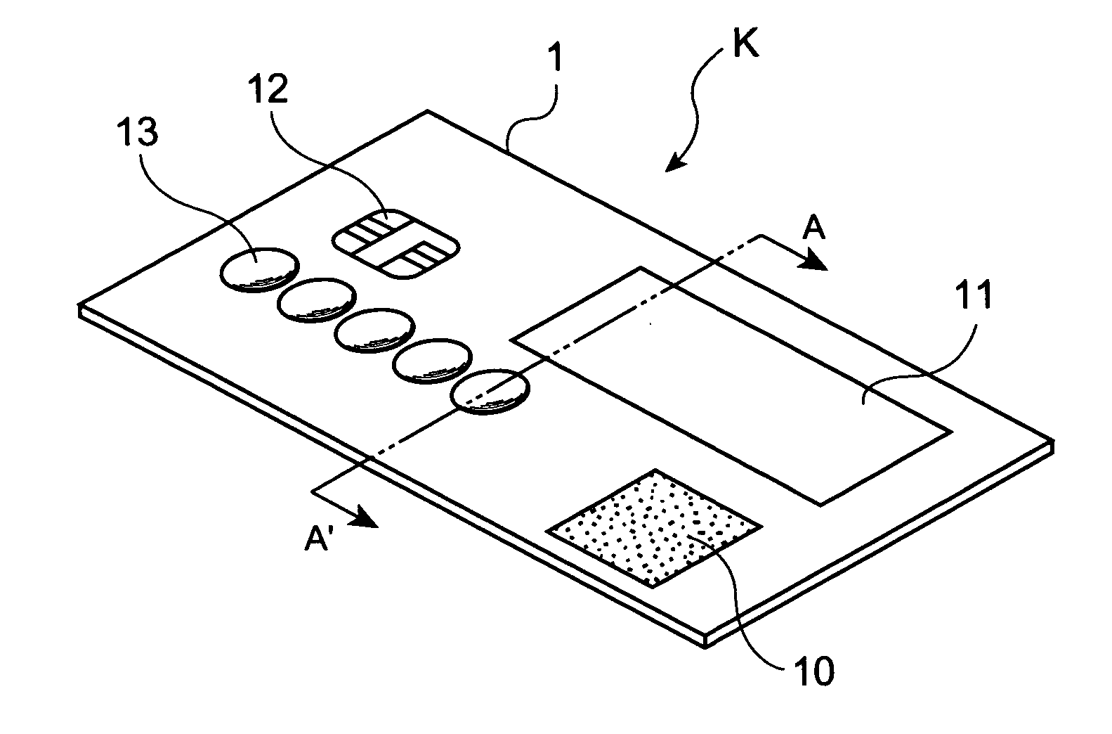
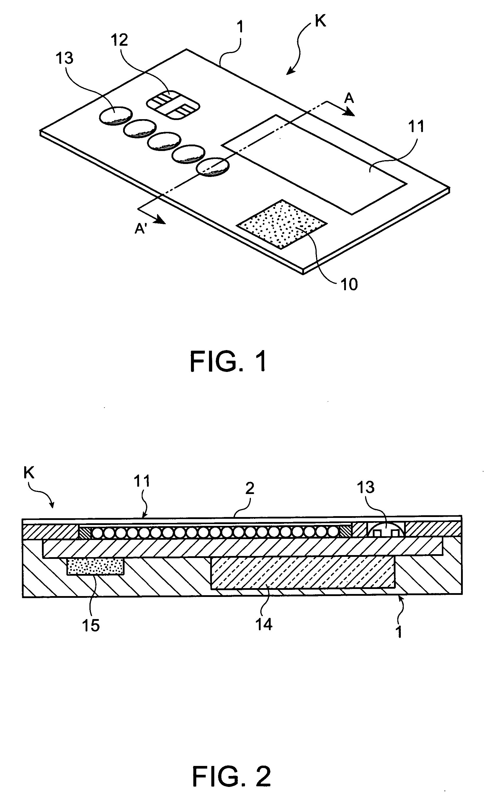
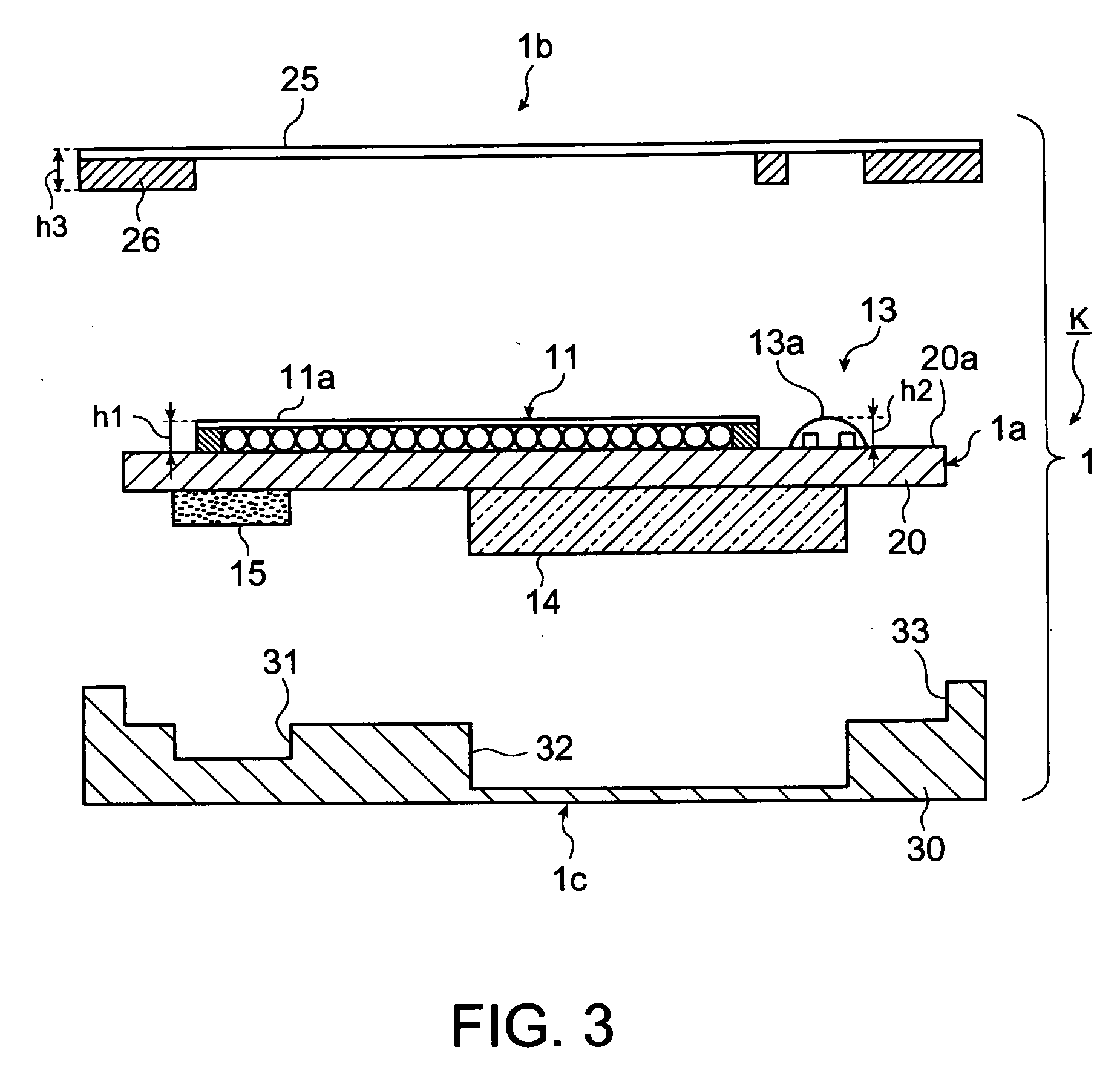
[0042]FIG. 1 is an oblique drawing showing an IC card K in the embodiment. FIG. 2 is a drawing showing a section A-A′ in FIG. 1, which is a sectional magnified drawing describing the sectional structure of the IC card K. FIG. 3 is a sectional magnified drawing of the IC card K, which is a deal drawing describing the structure of the IC card K in detail.

[0043] As shown in FIG. 1, the IC card K includes a card body 1, a fingerprint sensor 10 (a part of the function part), an Electrophoretic Display (hereafter EPD) 11 (a part of the function part and the display part), which is part of both the function part and the display part, a connecting IC terminal 12 (a part of the function part), and a membrane switch 13 (a part of the input means). Further, the card body 1 includes a polymer battery 14 and an IC chip 15 therein, as shown in FIGS. 2 and 3. Still further, the card body...

embodiment 2

of the IC Card

[0076] Embodiment 2 of the IC card in the invention is described with reference to the drawings.

[0077] In Embodiment 2, the same signs and numerals are used for the same structure as in the aforementioned Embodiment 1, and the descriptions thereof are simplified.

[0078]FIGS. 7 and 8 are sectional oblique drawings showing an IC card K in the embodiment. FIG. 7 is a drawing showing a section A-A′ in FIG. 1, which is a sectional magnified drawing describing the sectional structure of the IC card K. FIG. 8 is a sectional magnified drawing of the IC card K, which is a deal drawing describing the structure of the IC card K in detail.

[0079] As shown in FIG. 8, the height h1 represents the distance between a top surface 20a of the FPC 20 and the uppermost part 11a of the EPD 11, and the height h2 represents the distance between the top surface 20a of the FPC 20 and an uppermost part 13a of the membrane switch 13. The relations between the heights h1 and h2 are h1>h2. In othe...


PUM


Abstract

An integrated circuit card including: a card body; an input means formed on the card body; and a function part that operates corresponding to the input of the input means; wherein, in the direction of the thickness of the card body, an uppermost part of the input means is located at the same height as that of a surface of the card body, or is located more inwardly than the surface of the card body.

Description

RELATED APPLICATION INFORMATION [0001] This application claims priority to Japanese Patent Application No. 2004-323661, filed Nov. 8, 2004, whose contents are expressly incorporated herein by reference. BACKGROUND OF THE INVENTION [0002] 1. Technical Field [0003] The present invention relates to an integrated circuits card (IC card) having an input means such as switches, etc. [0004] 2. Related Art [0005] An IC card (smart card) has an integrated circuit (IC) chip embedded therein. Compared to magnetic stripe cards, IC cards are capable of providing a high information capacity, an improved security against forgery or unauthorized use, an ability to support diverse range of applications, and a reduced load for hosts (an ability of offline processing). Hence, IC cards have been applied in credit cards, cashing cards, and have started to be widely deployed in the fields of electric money, electric commerce, medical and health care, public transportation system, such as railways and bus...

Claims


Application Information

Patent Timeline
Patent Type & Authority Applications(United States)
IPC IPC(8): G06K19/06
CPCG06K19/0718G06K19/07345G06K19/077G06K19/07745H01H2231/05H01L2924/0002H01L2924/00
Inventor MIYAZAKI, ATSUSHI
Owner E INK CORPORATION
Why Eureka
Try Eureka