
Method and apparatus for removing cuttings from drilling fluids

a drilling fluid and cutting technology, applied in the field of drilling fluid recycling methods and equipment, can solve the problems of circuits often being unable to keep up with the throughput of drilling fluid required in drilling wells, and the cost of operating such a drilling fluid recycling system is substantial

Active Publication Date: 2006-05-11
HARDING DARIN MERLE
View PDF13 Cites 20 Cited by
  • Summary
  • Abstract
  • Description
  • Claims
  • Application Information

AI Technical Summary

Benefits of technology

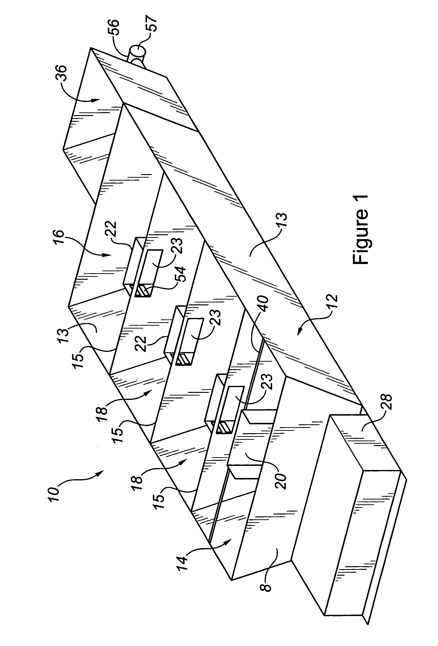
[0018] Broadly stated, one aspect of the present invention is a method for recycling drilling fluid used in drilling operations comprising the steps of directing a stream of drilling fluid containing solids into a flow-reversing barrier located in a receiving compartment of a settling tank, the settling tank further comprising a collecting compartment, the collecting compartment separated from the receiving compartment by a transverse wall, the wall defining an aperture with a flow-restricting baffle attached thereto, the flow-reversing barrier capable of causing the stream to reverse direction and flow around the barrier thereby causing at least some of the solids contained in the fluid to settle to the bottom of the tank, allowing the stream of fluid to fill the receiving compartment and pass through the aperture and flow-restricting baffle of the transverse wall as the fluid flows in a first direction from the receiving compartment to the collecting compartment, the flow-restricting baffle capable of causing at least some of the remaining solids contained in the fluid to settle to the bottom of the tank as the fluid flows through the aperture and baffle, allowing the fluid to flow in the first direction and fill the collecting compartment, extracting fluid from the collecting compartment for re-use in drilling operations, moving the settled solids on the bottom of the tank in the first direction towards an outlet located in the collecting compartment, and removing a mixture of fluid and solids from the outlet.

Problems solved by technology

In either case, the costs of operating such a drilling fluid recycling system are substantial.
While using the combination of settling tank and centrifuge is an improvement in comparison to using a centrifuge by itself, in practice, this circuit is often unable to keep up with the throughput of drilling fluid required in drilling a well.

Method used


Image

  • Method and apparatus for removing cuttings from drilling fluids
  • Method and apparatus for removing cuttings from drilling fluids
  • Method and apparatus for removing cuttings from drilling fluids

Examples


Embodiment Construction

[0031] The present invention is concerned with a method and apparatus for recycling drilling fluids used in the drilling of wells. Illustrated in FIGS. 1 and 2 is the preferred embodiment of the apparatus of the present invention. The apparatus 10 includes settling tank 12 which comprises of end walls 8 and 9, side walls 13 and bottom 19. Preferably, the dimensions of tank 12 are 50 feet long by 5 feet high by 10 feet wide. The preferred embodiment has three transverse walls 15 within tank 12 to form four compartments that are approximately 3,172 gallons in volume each for a total capacity of 12,688 gallons in tank 12. One compartment defined by a transverse wall 15 is receiving compartment 14 located adjacent to end wall 8 of tank 12. Another compartment defined by a transverse wall 15 is collecting compartment 14 located adjacent to end wall 9 of tank 12. The third transverse wall 15 defines the two intermediate compartments 18 between receiving compartment 14 and collecting compa...


PUM

PropertyMeasurementUnit
volumeaaaaaaaaaa
volumeaaaaaaaaaa
diameteraaaaaaaaaa

Abstract

The present invention is concerned with a method and apparatus for recycling drilling fluids used in the drilling of wells. The apparatus comprises a tank with a plurality of compartments. Used drilling fluid containing well cuttings or “solids” is pumped into a receiving compartment of the tank and directed towards a flow-reversing barrier. Reversal of the flow causes heavier solids to settle to the bottom of the tank. As fluid fills the receiving compartment, it flows downstream into an adjacent compartment by passing through a flow-restricting baffle that causes more solids to settle to the bottom of the tank. As fluid overflows from compartment to compartment in the tank, it passes through successive flow-restricting baffles causing further solids to settle to the bottom of the tank. When the fluid reaches the collecting compartment of the tank, it is removed to be used again in drilling operations. A conveyor extending along the bottom of the tank is used to move the settled solids to the collecting compartment, from which they are removed and pumped through a centrifuge to recover residual fluids.

Description

FIELD OF INVENTION [0001] The present invention relates to a method and apparatus for recycling drilling fluids used in the drilling of wells. BACKGROUND OF THE INVENTION [0002] The drilling of wells in the recovery of oil and gas typically comprises a rig drilling the well with a hollow drill string. As the well is being drilled, drilling fluids are pumped down the bore of the string. The drilling fluid passes through openings in the drill bit and returns to the surface through the annulus surrounding the string, carrying the cuttings produced by the drill bit. The drilling fluid is then recycled to remove the cuttings so that it may be used again. [0003] Traditional methods of recycling drilling fluid include using a centrifuge to separate the liquid from the cuttings. In large drilling operations, to keep up with the volume of drilling fluid used, it is necessary to use either a very large centrifuge or to use a multitude of centrifuges. In either case, the costs of operating suc...

Claims


Application Information

Patent Timeline
Patent Type & Authority Applications(United States)
IPC IPC(8): B01D21/00
CPCB01D21/0003B01D21/003B01D21/0042B01D21/2461B01D2221/04
Inventor HARDING, DARIN MERLE
Owner HARDING DARIN MERLE
Learn More