
Methods of generating a gas in a plugging composition to improve its sealing ability in a downhole permeable zone

a technology of a plugging composition and a gas, which is applied in the direction of sealing/packing, wellbore/well accessories, chemistry apparatus and processes, etc., can solve the problems of inability to provide service by such fluids, the fluid circulation in the wellbore is too low to allow for further drilling of the wellbore, and the other fluids used in servicing the wellbore may also be lost to the subterranean formation. to achieve the effect of improving the sealing ability

Inactive Publication Date: 2006-04-20
HALLIBURTON ENERGY SERVICES INC
View PDF99 Cites 61 Cited by
  • Summary
  • Abstract
  • Description
  • Claims
  • Application Information

AI Technical Summary

Benefits of technology

[0008] Methods of servicing a wellbore include generating a gas in a plugging composition in situ within a permeable zone in the wellbore, thereby improving the ability of the plugging composition to seal the permeable zone. The gas may be generated via a chemical reaction by, for example, introducing first and second reactants to the plugging composition that can react at ambient temperatures in the wellbore to produce the gas. In an embodiment, the first reactant comprises a nitrogen-generating material, and the second reactant comprises an alkaline aqueous solution or an oxidizing agent. In another embodiment, the first reactant comprises a hydrogen generating material, and the second reactant comprises an alkaline aqueous solution. In yet another embodiment, the first reactant comprises a carbon dioxide generating chemical and the second reactant comprises an acid or acid generating chemical.

Problems solved by technology

In addition to the fracturing fluid, other fluids used in servicing a wellbore may also be lost to the subterranean formation while circulating the fluids in the wellbore.
As a result, the service provided by such fluid is more difficult to achieve.
For example, a drilling fluid could be lost to the formation, resulting in the circulation of the fluid in the wellbore being too low to allow for further drilling of the wellbore.
Also, a cement / sealant composition could be lost to the formation as it is being placed in the wellbore, thereby rendering the cementing / sealing operation ineffective in maintaining isolation of the formation.
The loss of such fluids increases the cost of the overall operation due to the prolonged rig time required, the fluids being relatively expensive, and possibly a need to install casing.
Permeable zones in the subterranean formation may further allow water to undesirably flow from the formation into the wellbore during primary and secondary cementing operations, resulting in the influx and crossflows of water through cement slurries that have been placed in the wellbore.
Those flow channels could allow the water to flow from one subterranean zone to another such that zonal isolation is no longer achieved.
Further, the water can intermix with and dilute the cement slurry, causing deterioration of the cement properties such as its density, its final compressive strength, and its rheology.
The isolation of the subterranean formation also may be compromised by permeable zones present in the annulus and / or the wall of the casing in the wellbore.
Permeable zones such as voids in the cement column placed in the annulus may result from an incomplete fill in of the annulus during primary cementing.
Moreover, the cement column may experience impacts and shocks generated by subsequent drilling, pressure testing, hydraulic fracturing, or other well operations.
Unfortunately, conventional cement suffers from the drawback of being brittle and fragile and thus often cannot sustain such stress.
Consequently, cracks or voids may form in the cement column and / or the casing wall.
The use of such plugging compositions, however, does not necessarily ensure that fluid will be prevented from flowing through the permeable zones in which they are placed.
The plugging compositions may be unable to withstand the pressures applied by the fluids in the wellbore or the formation fluids due to, for example, an insufficient amount of friction between the compositions and adjacent surfaces in the wellbore.
Further, the plugging compositions may lack the the ability to resiliently conform to the changes in the sizes and shapes of the permeable zones that often occur during the follow up operations in the wellbore in which they are used.
Therefore, fluid may undesirably leak through areas of the permeable zones where the plugging compositions have debonded from the perimeters of those zones.

Method used


Image

  • Methods of generating a gas in a plugging composition to improve its sealing ability in a downhole permeable zone
  • Methods of generating a gas in a plugging composition to improve its sealing ability in a downhole permeable zone

Examples


example 1

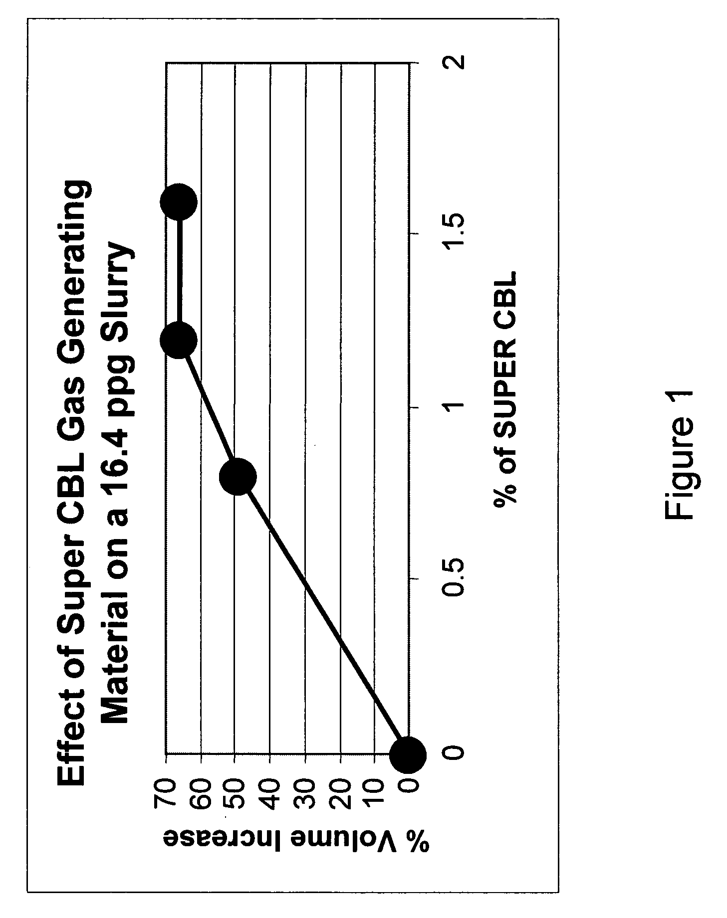
[0046] Various concentrations of a coated aluminum powder known as SUPER CBL additive available from Halliburton Energy Services, Inc. were added as the gas generating material to different samples of a 16.4 ppg class H cement slurry, thereby generating H2 in each sample. The % volume increase of each sample as a result of the generation of the gas was then determined at a temperature of 75° F. and at atmospheric pressure. Slurries with different amounts of SUPER CBL were allowed to set in cylindrical container at atmospheric pressure and 80° F., and once set the volume of the set material in each case was measured. FIG. 1 is a graph showing the % volume increase of the cement slurry as a function of the concentration of the SUPER CBL gas generating material. As illustrated in FIG. 1, the percentage by which the volume of the slurry increased experienced an increase as the concentration of the SUPER CBL gas generating material was increased from about 0% to about 1.2%, and then it l...

example 2

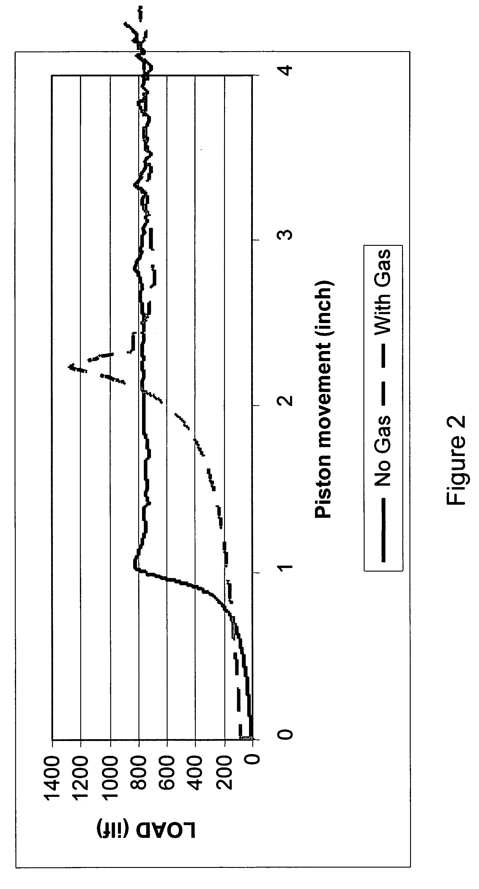
[0047] A FLEXPLUG composition containing gas generated using SUPER CBL was placed in an L-shaped tube having a fracture at its base. A piston in the tube was used to apply an increasing load (i.e., force) to the top of the FLEXPLUG composition, thereby forcing it into and through the fracture. This procedure was repeated for a FLEXPLUG composition containing no gas. FIG. 2 is a graph of the load as a function of the piston movement for each FLEXPLUG composition. The peaks in FIG. 2 represent the when the FLEXPLUG compositions were extruded into the fracture. As illustrated by FIG. 2 and Table 1 below, the load required to extrude the FLEXPLUG composition containing gas was greater than that required to extrude the FLEXPLUG composition containing no gas. Thus, the composition containing gas exhibited greater friction relative to adjacent surfaces of the tube than the composition containing no gas. Further, the distance and therefore duration of piston movement required to extrude the...


PUM

PropertyMeasurementUnit
Sizeaaaaaaaaaa
Temperatureaaaaaaaaaa
Forceaaaaaaaaaa

Abstract

Methods of servicing a wellbore include generating gas in a plugging composition in situ within a permeable zone in the wellbore, thereby improving the ability of the plugging composition to seal the permeable zone. The gas may be generated via a chemical reaction by, for example, introducing first and second reactants to the plugging composition that can react at ambient temperatures in the wellbore. In an embodiment, the first and second reactants are concurrently pumped into the wellbore via separate flow paths within two concentric conduits to the permeable zone where they are allowed to contact each other in the presence of the plugging composition. In another embodiment, the first reactant, the second reactant, and a retarder for slowing the reaction between the two reactants are concurrently pumped to the permeable zone. In yet another embodiment, one of the reactants is encapsulated to delay a reaction between the two reactants.

Description

FIELD OF THE INVENTION [0001] The present invention generally relates to recovering materials from a subterranean formation, and more particularly to methods of generating a gas in a plugging composition in situ within a downhole permeable zone such as a formation fracture, thereby improving the ability of the plugging composition to seal the permeable zone. BACKGROUND OF THE INVENTION [0002] A natural resource such as oil or gas residing in a subterranean formation can be recovered by drilling a well into the formation. In particular, a wellbore is typically drilled down to the subterranean formation while circulating a drilling fluid through the wellbore. After the drilling is terminated, a string of pipe, e.g., casing, is run in the wellbore. Primary cementing is then usually performed whereby a cement slurry is pumped down through the string of pipe and into the annulus between the string of pipe and the walls of the wellbore to allow the cement slurry to set into an impermeable...

Claims


Application Information

Patent Timeline
IPC IPC(8): E21B43/00E21B33/00
CPCC09K8/516E21B33/138
Inventor SANTRA, ASHOK K.REDDY, B. RAGHAVAZAMORA, FRANKGOMEZ, GIDDO ANTONIO OCANAMORGAN, RONNIE G.SAVERY, MARK R.
Owner HALLIBURTON ENERGY SERVICES INC
Learn More