Display device and method
a technology of liquid crystal display and display device, which is applied in the direction of optics, instruments, optical light guides, etc., can solve the problems of inability to emphasize the sub-lcd panel, the design of the lcd device cannot be diversified, and the height of the sub-lcd panel cannot be relatively high
- Summary
- Abstract
- Description
- Claims
- Application Information
AI Technical Summary
Benefits of technology
Problems solved by technology
Method used
Image

Examples
embodiment 1
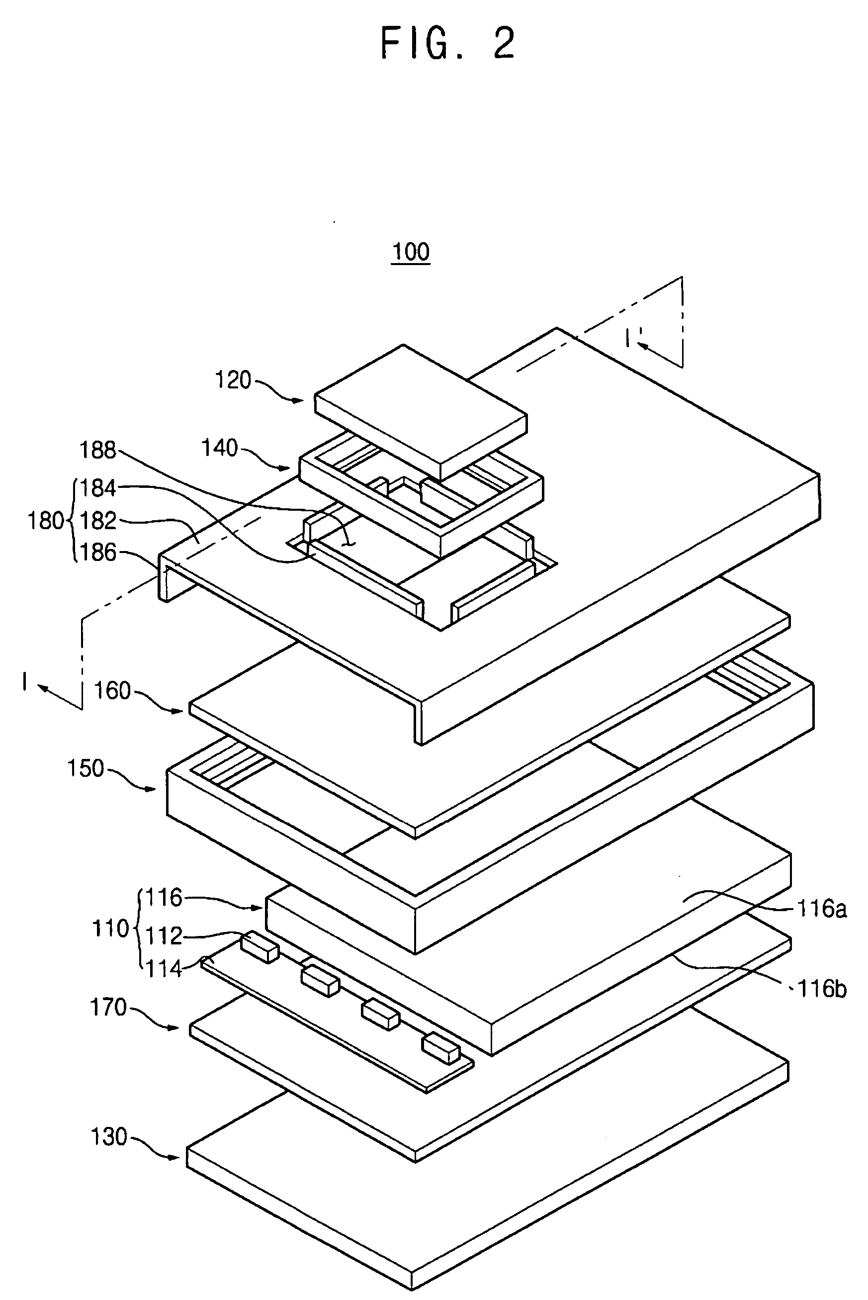
[0035]FIG. 2 is an exploded perspective view illustrating a first exemplary embodiment of an LCD device according to the present invention. FIG. 3 is a cross-sectional view of an exemplary first LCD panel and an exemplary receiving container taken along line I-I′ in FIG. 2.
[0036] Referring to FIGS. 2 and 3, an LCD device 100 includes a backlight assembly 110, a first LCD panel 120, a second LCD panel 130, a first mold frame 140, a second mold frame 150, a first optical sheet 160, a second optical sheet 170, and a receiving container 180.
[0037] The backlight assembly 110 includes a plurality of light emitting diodes (“LEDs”) 112, a printed circuit board (“PCB”) 114, and a light guiding plate 116. While LEDs are disclosed as the light source for the backlight assembly 110 of this embodiment, alternate light sources would also be within the scope of these embodiments.
[0038] The LEDs 112 generate light in response to an external power. The LEDs 112, for example, include a white LED e...
embodiment 2
[0056]FIG. 4 is an exploded perspective view illustrating a second exemplary embodiment of an LCD device according to the present invention. FIG. 5 is a cross-sectional view of an exemplary first LCD panel and an exemplary receiving container taken along line II-II′ in FIG. 4. The LCD device of the present embodiment is substantially identical to the LCD device of Embodiment 1 except for a receiving container and a first mold frame. Thus, any further description for the substantially same elements will be omitted.
[0057] Referring to FIGS. 4 and 5, the LCD device 200 includes a backlight assembly 110, a first LCD panel 120, a second LCD panel 130, a tape panel 240, a second mold frame 150, a first optical sheet 160, a second optical sheet 170, and a receiving container 280.
[0058] The receiving container 280 includes a substantially planar bottom plate 282, a plurality of guides 284, and a plurality of sidewalls 286. A central portion of the bottom plate 282 of the receiving contain...
embodiment 3
[0066]FIG. 6 is an exploded perspective view illustrating a third exemplary embodiment of an LCD device according to the present invention. FIG. 7 is a cross-sectional view of an exemplary first LCD panel and an exemplary receiving container taken along line III-III′ in FIG. 6. The LCD device of the present embodiment is substantially identical to the LCD device of Embodiment 2 except for a receiving container. Thus, any further description for the substantially same elements will be omitted.
[0067] Referring to FIGS. 6 and 7, an LCD device 300 includes a backlight assembly 110, a first LCD panel 120, a second LCD panel 130, a protruded portion 340, a second mold frame 150, a first optical sheet 160, a second optical sheet 170, and a receiving container 380.
[0068] The receiving container 380 includes a bottom plate 382 and a plurality of sidewalls 386. The bottom plate 382 may be substantially planar and generally parallel to the first LCD panel 120. A central portion of the bottom...
PUM
 Abstract
Description
Claims
Application Information
 - R&D
- Intellectual Property
- Life Sciences
- Materials
- Tech Scout
- Unparalleled Data Quality
- Higher Quality Content
- 60% Fewer Hallucinations
Browse by: Latest US Patents, China's latest patents, Technical Efficacy Thesaurus, Application Domain, Technology Topic, Popular Technical Reports.
© 2025 PatSnap. All rights reserved.Legal|Privacy policy|Modern Slavery Act Transparency Statement|Sitemap|About US| Contact US: help@patsnap.com