Solenoid valve

Inactive Publication Date: 2006-04-20
MITSUBISHI ELECTRIC CORP
View PDF6 Cites 10 Cited by
  • Summary
  • Abstract
  • Description
  • Claims
  • Application Information

AI Technical Summary

Benefits of technology

[0014] Because the valve port is thereby annularly disposed in the diaphragm blocking the halfway portion of the channel, the receiving pressure acting on the valve disk can be reduced, and the flow rate brought about by the solenoid valve can be increased without increasing the electromagnetic attraction required for displacing the valve disk. Further, either one or both of the input port and the output port are disposed laterally to the valve port, thereby enabling the pressure of the fluid to act on the valve from the direction lateral to the valve port. As a result, the fluid can responsively flow into the valve port at the time of valve-disk opening, and accordingly, the follow-up of the fluid is accelerated at the time of valve opening.
[0016] Thereby, the weight reduction of its valve disk can be achieved, and the valve disk does not easily incline even if a difference in pressure arises in the periphery of the valve disk.
[0018] Thereby, the fluid does not flow through the other divided body, enabling the sealing property thereof to be improved.

Problems solved by technology

However, this results in the reduced lifetime of the valve disk and the increased operation sound.
This results in the reduced lifetime of the valve disk, the increased operation sound, and the enlarged housing.
Moreover, because the conventional solenoid valve is arranged such that the valve disk is slidably engaged on the inner face of the guide cylinder standing up from the periphery of the valve port, it has been difficult to reduce the weight of the solenoid valve.

Method used


Image

  • Solenoid valve
  • Solenoid valve
  • Solenoid valve

Examples


first embodiment

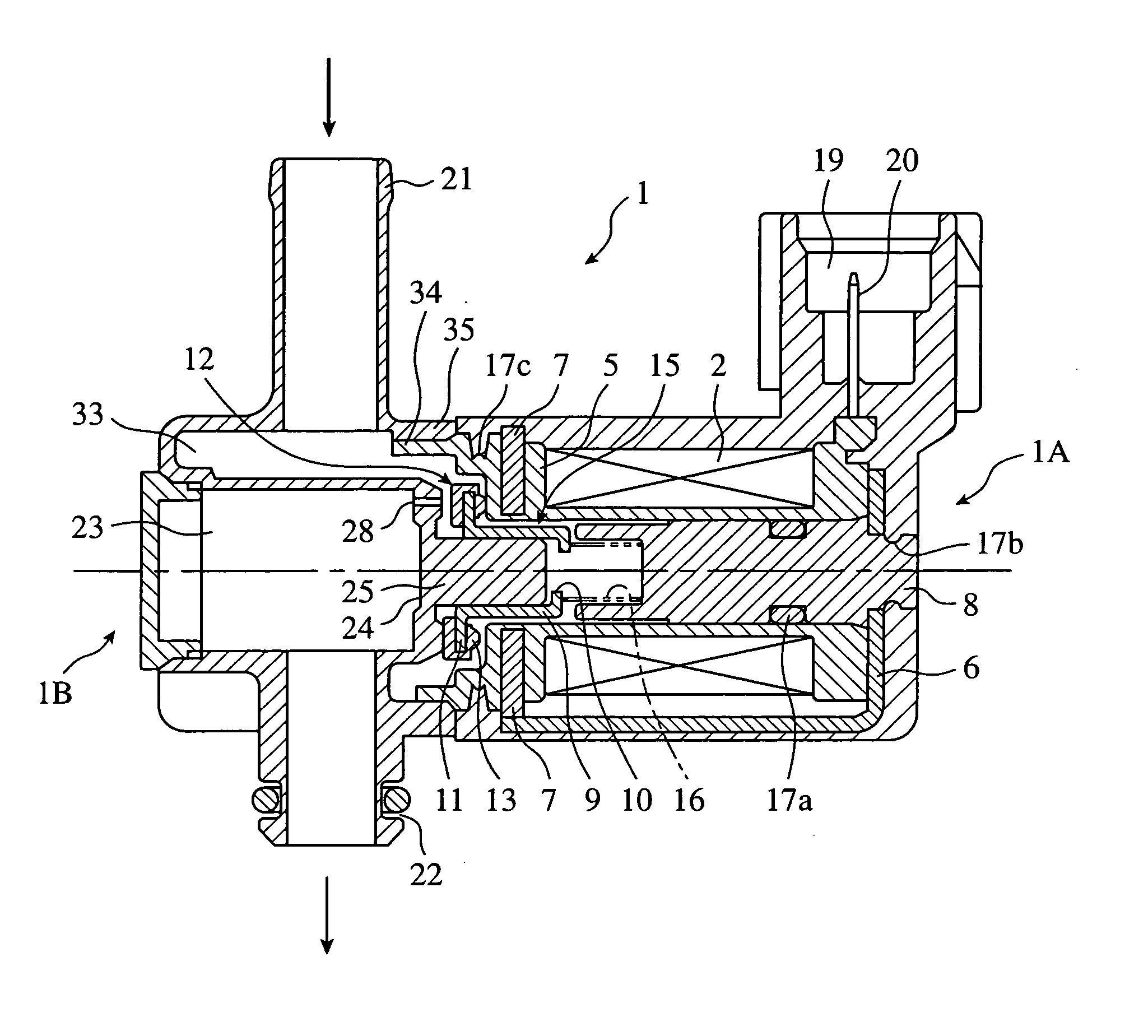
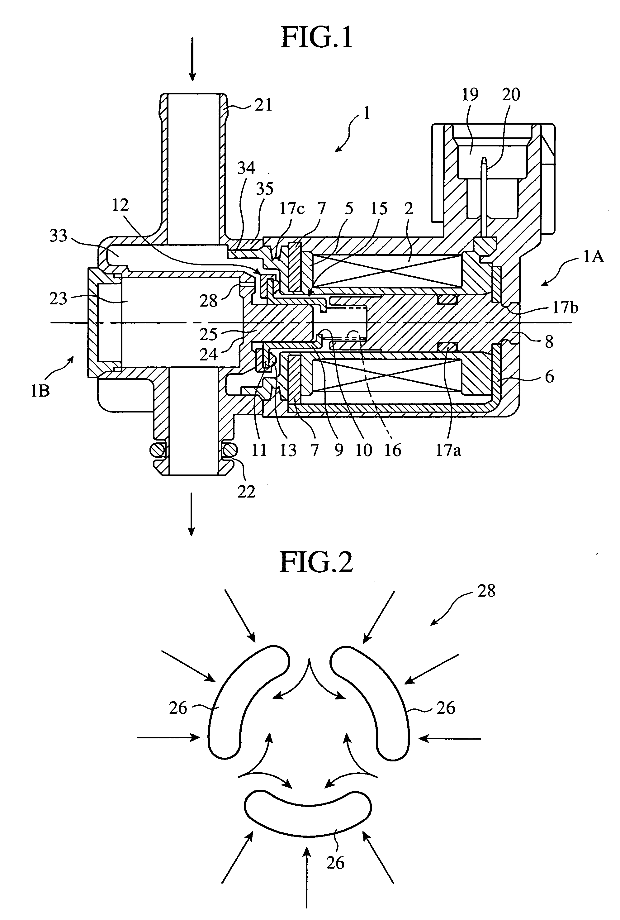
[0037]FIG. 1 is a cross sectional view showing a solenoid valve according to the present invention, the upper half showing the valve-opening state thereof, and the lower one showing the valve-closing state thereof, respectively. FIG. 2 is a schematic plan view showing the shape of the valve port thereof. FIG. 3 is a schematic sectional view showing the state in which the fluid is flowing into the valve port thereof. FIG. 4 is a schematic plan view showing the valve port along which a rib is provided. FIG. 5 is a schematic plan view showing the modification of the rib shown in FIG. 4. FIG. 6 is a cross sectional view taken along the line a-a in FIG. 5. FIG. 7 is a schematic sectional view showing the state in which the valve disk thereof is engaged around the guide boss thereof. FIG. 8 is a cross sectional view showing the guide boss. FIG. 9 is a view corresponding to FIG. 1 showing a modification. FIG. 10 is a view corresponding to FIG. 1 showing another modification. FIG. 11 is a p...

second embodiment

[0067]FIG. 15 is a plan view showing the second embodiment of a solenoid valve according to the present invention. FIG. 16 is a side elevation view of the FIG. 15. And FIG. 17 is a front view of the FIG. 15. The same parts are designated by similar numerals in Embodiment 1, and the repetitive explanation is omitted for brevity's sake.

[0068] Embodiment 2 is, as shown in FIG. 17, a solenoid valve arranged such that the input port 21 and the output port 22 are disposed on a straight line. The solenoid valve can be made compact, and provide an advantageous vehicle layout.


PUM


Abstract

A guide boss is provided in a diaphragm blocking the halfway portion of a channel; a valve disk is formed in the shape of a cylinder; the inner face of this cylinder-shaped valve disk is slidably engaged around the guide boss; and further, a valve port consisting of a plurality of long bores are formed in a diaphragm surrounding the guide boss. Thereby, fluid can responsively flow into the valve port when the valve disk is opened, and the follow-up of the fluid is accelerated.

Description

TECHNICAL FIELD [0001] The present invention relates to a solenoid valve used for the flow rate control of fluid, and more particularly to a solenoid valve installed in piping connecting a canister, which adsorbs volatilized gas from a fuel tank, to the inlet pipe of an engine. BACKGROUND ART [0002] A canister adsorbing the volatilized gas and a solenoid valve are provided in halfway in piping feeding volatilized gas from a fuel tank into an engine. The output port of the solenoid valve is connected to the piping on the canister side, and the input port thereof is connected to an inlet pipe supplying fuel-air mixture into the engine, respectively. When the solenoid valve is opened, the negative pressure formed thereby in the inlet pipe aspirates the volatilized gas adsorbed in the canister, and the gas is fed into the engine. [0003] The solenoid valve is opened and closed by energizing or de-energizing an electromagnetic coil. Energizing the electromagnetic coil generates an electro...

Claims


Application Information

Patent Timeline
IPC IPC(8): F16K31/02F02M25/08F16K31/06
CPCF02M25/0836F02M2025/0845F16K31/0658Y10T137/8667Y10T137/86759
Inventor TAKAHASHI, MASAJIITO, TAKAYUKI
Owner MITSUBISHI ELECTRIC CORP
Why Eureka
Try Eureka