
Power transmission unit

Inactive Publication Date: 2006-04-20
BORGWARNER INC
View PDF2 Cites 22 Cited by
  • Summary
  • Abstract
  • Description
  • Claims
  • Application Information

AI Technical Summary

Benefits of technology

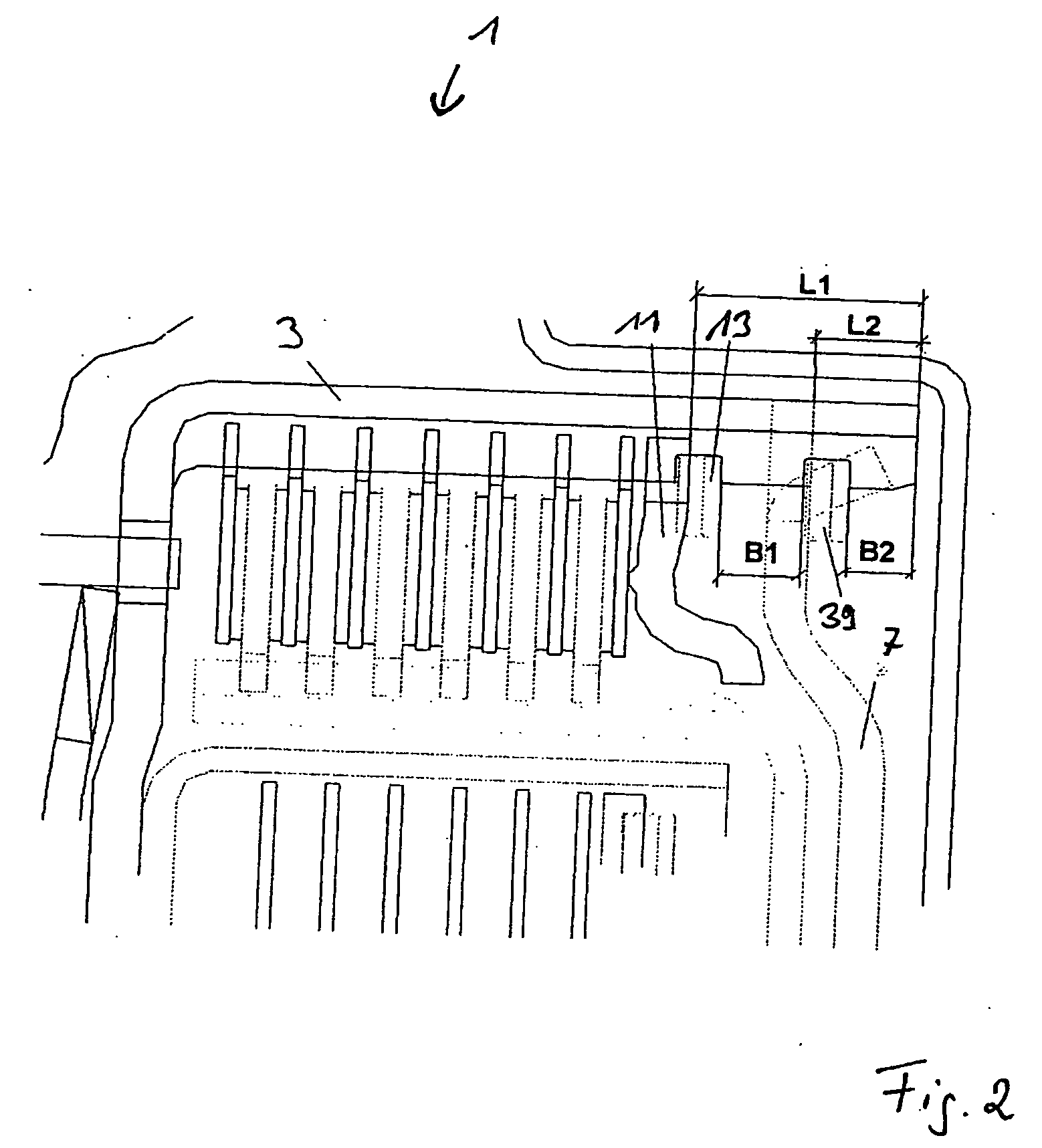
[0008] The invention is based on the concept of fastening the drive plate exclusively on the clutch side in order to transmit the forces acting in the axial direction on the drive plate into the region of the disk carrier, which extends axially from the drive plate toward the disks. Since the region of the disk carrier that extends axially outward from the drive plate no longer has a holding function, it can be embodied in a correspondingly shortened form. In principle, the embodiment of the power transmission unit according to the invention makes it possible for the disk carrier to extend in the axial direction only to the drive plate and no further.

Problems solved by technology

Frequently, the available axial space is very limited, particularly in the region of the disk carrier itself, because an additional damper or dual mass flywheel is usually situated here.

Method used


Image

  • Power transmission unit
  • Power transmission unit
  • Power transmission unit

Examples


Embodiment Construction

[0049] In the figures, parts that are the same or function in the same manner have been provided with the same reference numerals.

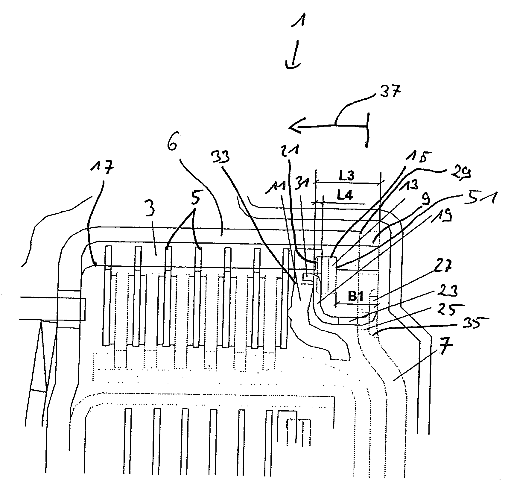
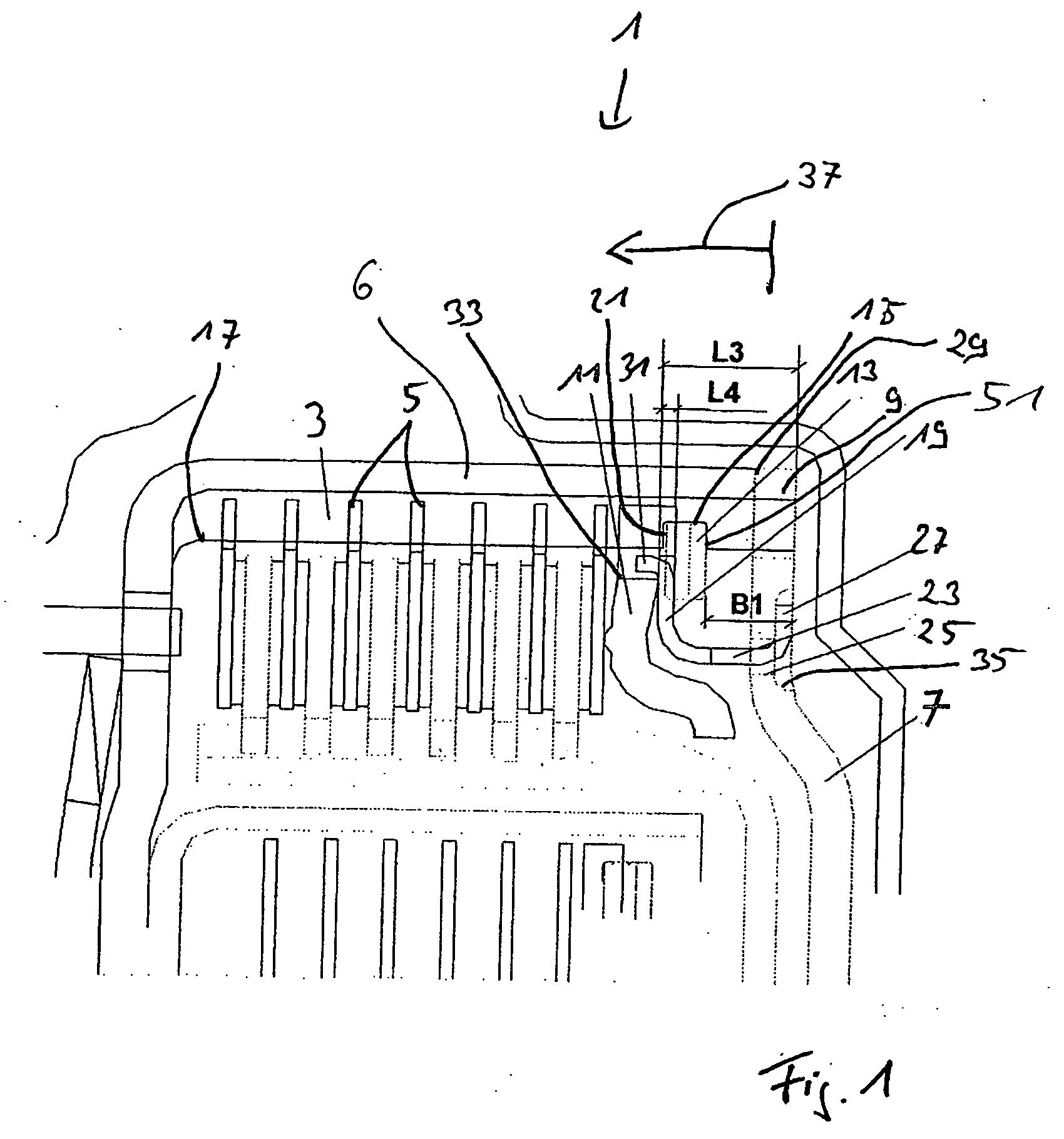
[0050]FIG. 1 shows a section through a part of a power transmission unit 1. The invention is explained by way of example in conjunction with a double clutch, but can also be implemented in all power transmission units equipped with a disk carrier and a drive plate.

[0051] The double clutch has an external disk carrier 3 that carries a number of axially spaced external disks 5 that are connected in a non-rotating fashion to the external disk carrier 3 by means of plug-in teeth. The external teeth of the external disks 5 engage in axial ribs 17 and axial grooves 43 of the disk carrier 3 that are distributed in alternating fashion over the circumference, on the side oriented toward the disks. The axial ribs 17 and axial grooves 43 extend along a cylindrical section 6 of the disk carrier 3. A drive plate 7 situated in the axial end region of the external dis...


PUM


Abstract

The invention relates to a power transmission unit, in particular a multiple disk clutch or friction brake, in which a disk carrier that has at least one disk, which has external teeth and is fastened to it in a non-rotating fashion, which disk carrier, in a cylinder section and oriented toward the disk, has axial grooves and axial ribs distributed over the circumference in alternating fashion and is connected to a hub on one side by means of a drive plate spaced axially apart from the disks; a non-rotatable connection between the drive plate and the disk carrier is produced by means of plug-in teeth in order to transmit a torque. The object of the invention is to propose a power transmission unit (1) in which the axial space is reduced. This object is attained in that additional means are provided for axially fastening the drive plate to the disk carrier; the axial fixing means are embodied so that axial forces that the drive plate exerts on the disk carrier exclusively engage the region of the disk carrier that extends axially from the drive plate in the direction of the disks.

Description

CROSS-REFERENCE TO RELATED APPLICATIONS [0001] This application claims priority to European Patent Application No. 04 023814.9 filed on Oct. 6, 2004. FIELD OF THE INVENTION [0002] The invention relates to a power transmission unit. BACKGROUND OF THE INVENTION [0003] A power transmission unit of the species-defining type is described, for example, in EP 1,422,430 A1. Usually, in multiple disk clutches, for example in a double clutch, the disk pack and the drive plate are each fixed axially in the disk carrier by means of a snap ring. As a rule, a suitable snap ring thickness is also used here to set the air space of the disks in the disk pack. In addition, the drive plate should also be axially fixed with as little play as possible. [0004] In order to prevent the drive plate from chattering within the possible play in the circumference direction when the internal combustion engine is idling, the axial fixing of the drive plate can be preloaded in the axial direction. This generates a...

Claims


Application Information

Patent Timeline
IPC IPC(8): F16D13/52
CPCF16D13/52F16D13/58F16D13/683F16D2300/12F16H57/02F16H57/035
Inventor HEINRICH, JOHANNESHAUCK, HANS JUERGEN
Owner BORGWARNER INC
Learn More