
Drying apparatus, washing/drying apparatus, and operation methods of the apparatuses

a technology of drying apparatus and operation method, which is applied in the field of drying apparatus, can solve the problems of high temperature air in the drying chamber, increased energy consumption for drying the thing to be dried, and exhaustion to the outside, so as to improve the durability of the compressor, reduce the time for a refrigeration cycle, and prevent liquid backflow.

Inactive Publication Date: 2006-04-20
SANYO ELECTRIC CO LTD
View PDF6 Cites 19 Cited by
  • Summary
  • Abstract
  • Description
  • Claims
  • Application Information

AI Technical Summary

Benefits of technology

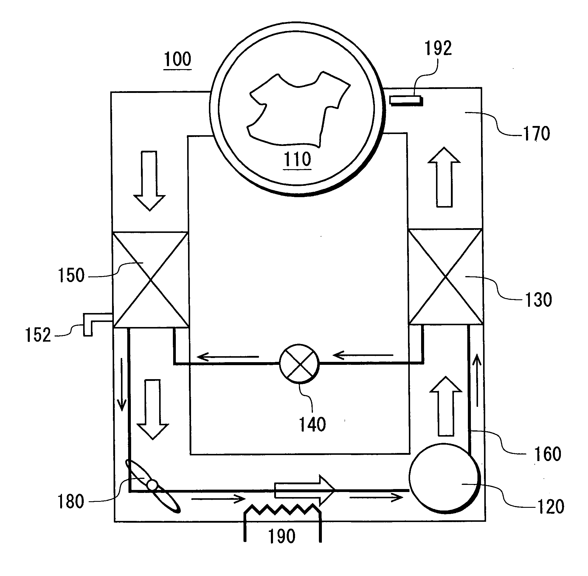
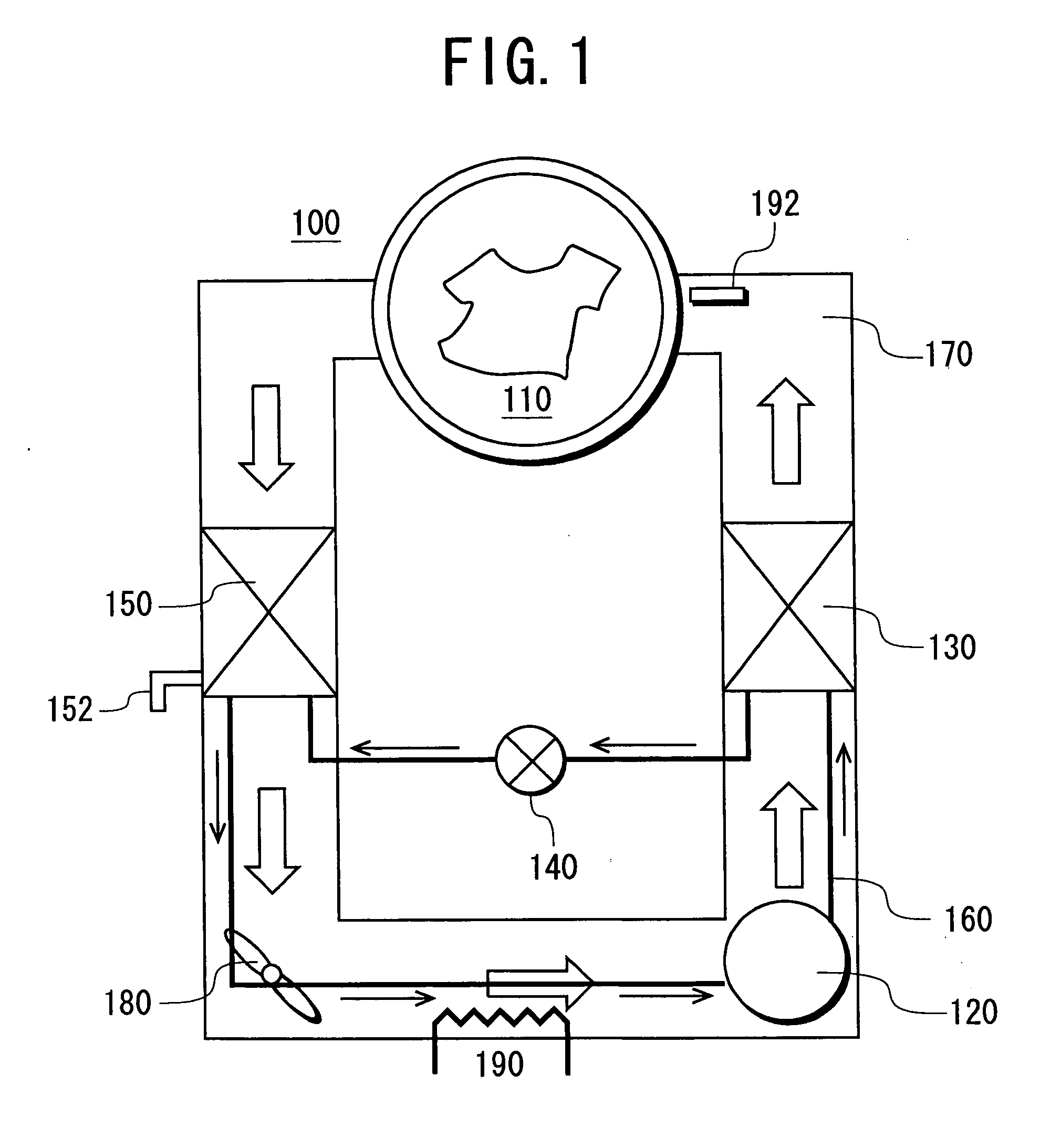
[0005] Therefore, it is an object of the present invention to provide an energy-saving drying apparatus which prevents liquid backflow, reduces time for a refrigeration cycle to be in a steady state, and can significantly reduce a time required for drying.

Problems solved by technology

Moreover, the high-temperature air in the drying chamber, by which the thing to be dried has been dried, is exhausted to the outside.
In such a drying apparatus, it requires a long time until the thing to be dried dries.
Therefore, energy consumption for drying the thing to be dried increases, and there has been a problem that energy costs such as electricity and gas charges soar.
Hence, there has been a problem that the compressor is damaged or a life of the compressor is significantly reduced.
Further, this drying apparatus has a problem that it takes some time for a refrigerant circuit to be in a steady state as compared with the drying apparatus using the heater as the heat source.

Method used


Image

  • Drying apparatus, washing/drying apparatus, and operation methods of the apparatuses
  • Drying apparatus, washing/drying apparatus, and operation methods of the apparatuses
  • Drying apparatus, washing/drying apparatus, and operation methods of the apparatuses

Examples


embodiment 1

[0062] Next, an operation in Embodiment 1 of a washing / drying apparatus 200 will be described with FIGS. 8 to 14.

[0063] As shown in FIG. 8, a thing to be washed and a predetermined amount of washing powder corresponding to an amount of the thing to be washed are thrown into an inner drum 204 (drying chamber 210). When a power switch and a start switch are operated among the above-described operation switches, a control device starts a washing operation (S11). Moreover, the control device opens a water supply valve of an unshown water supply passage to open the water supply passage. Accordingly, water is supplied into the inner drum 204 (drying chamber 210) from the water source. It is to be noted that, at this time, a draining valve of the draining passage is closed by the control device. When a predetermined amount of water is stored in the inner drum 204 (drying chamber 210), the control device closes the water supply valve to close the water supply passage. Accordingly, water su...

embodiment 2

[0071] Next, an operation in Embodiment 2 of a washing / drying apparatus 200 will be described with FIGS. 15 to 19.

[0072] As shown in FIG. 15, a basic operation is similar to that in Embodiment 1, but operations after a spin-drying operation (S24) are different from those in Embodiment 1. Therefore, a description is omitted for operations ranging from a washing operation (S21) to a rinsing operation (S23) that are similar to those in Embodiment 1, and the operations after the spin-drying operation (S24) will be described.

[0073] As shown in FIG. 16, a control device starts a preheat operation (S25) during the spin-drying operation (S24). This preheat operation (S25) branches into a first-stage preheating to start an electric heater 290 and a second-stage preheating to start a compressor 220, as shown in FIG. 17. First, when a temperature sensor 292 provided in an air circulation path 270 in the vicinity of an entrance of an inner drum 204 (drying chamber 210) registers a temperature...


PUM


Abstract

An object is to provide an energy-saving drying apparatus which prevents liquid backflow, reduces time for a refrigeration cycle to be in a steady state, and can significantly reduce a time required for drying. The drying apparatus comprises: a drying chamber for accommodating a thing to be dried; a refrigerant circuit in which a compressor, a radiator, a decompression device and a heat sink are successively connected to one another in an annular form via a piping; an air circulation path in which air in the drying chamber exchanges heat with the radiator and the heat sink and circulates; and air circulation means provided in the air circulation path for circulating the air, wherein at least part of the piping from the decompression device to the compressor of the refrigerant circuit is provided within the air circulation path, and the air circulation path is equipped with heating means.

Description

BACKGROUND OF THE INVENTION [0001] The present invention relates to a drying apparatus for drying a thing to be dried by use of a refrigeration cycle, and more particularly relates to a drying apparatus which prevents a refrigerant from being drawn into a compressor in a liquid state at the start of a drying operation and which can bring a steady state stably and in a short time. [0002] A general drying apparatus has heretofore used an electric heater or a gas combustion heater as a heat source. After heating outside air by the heat source including the electric heater or the combustion heater to obtain high-temperature air, the air is blown into a drying chamber in which a thing to be dried is accommodated to dry the thing to be dried in the drying chamber. Moreover, the high-temperature air in the drying chamber, by which the thing to be dried has been dried, is exhausted to the outside. In such a drying apparatus, it requires a long time until the thing to be dried dries. Therefo...

Claims


Application Information

Patent Timeline
Patent Type & Authority Applications(United States)
IPC IPC(8): F25D17/06F25B29/00F26B3/00
CPCD06F58/206F25B9/008F25B2309/061
Inventor ONO, KOJITOMOCHIKA, KAZUYOSHI
Owner SANYO ELECTRIC CO LTD
Learn More