
Floor sheet assembly

a technology of floor sheet and assembly, which is applied in the direction of building components, constructions, buildings, etc., can solve the problems of increasing the gross weight of the vehicle, the floor of the vehicle, and not being appropriate, and achieve the effect of efficient absorption of noise generated

Inactive Publication Date: 2006-04-20
UBE NITTO KASEI CO LTD
View PDF1 Cites 16 Cited by
  • Summary
  • Abstract
  • Description
  • Claims
  • Application Information

AI Technical Summary

Benefits of technology

[0004] The present invention seeks to provide a floor sheet assembly which is able not only to restrain an increase in a gross weight of a vehicle, but also to increase sound absorption as well as stiffness of the vehicle.
[0006] The invention described above, which introduces the honeycomb structure that has a plurality of spaces defined by the intermediate member and the pair of sheet members, excels in its light weight and high stiffness. If the floor sheet assembly according to the invention is applied to a floor of a vehicle, for example, it is possible not only to restrain an increase in a gross weight of the vehicle but also to increase sound absorption and stiffness of the floor.
[0008] The invention described above, which provides a larger space within the intermediate member without increasing a height of the projections, is able to increase not only stiffness but also impulse absorption and sound absorption of the floor sheet assembly.
[0011] Because the holes are bored at least on one side of the floor sheet assembly according to the invention described above, it is possible to guide noise reaching the sheet member, which lies on the same side, into a honeycomb structure so that the noise is efficiently absorbed, even if the sheet member does not breathe.
[0013] According to the invention described above, the surface member which usually does not breathe has the holes, which are aligned with the holes bored in the sheet member. As a result, it is possible for the floor sheet assembly not only to have a honeycomb structure efficiently absorb noise generated in a cabin, but also to satisfy an owner of a vehicle by providing free selection of a favorite surface material.

Problems solved by technology

However, it has not been appropriate that the floor of a vehicle should be covered with a conventional floor sheet without modification, which is developed for application to a house.
This is attributed to the fact that this conventional floor sheet is adapted to be relatively thick so as to increase its sound absorption and stiffness, which leads to an increase in a gross weight of the vehicle.

Method used


Image

  • Floor sheet assembly
  • Floor sheet assembly
  • Floor sheet assembly

Examples


example

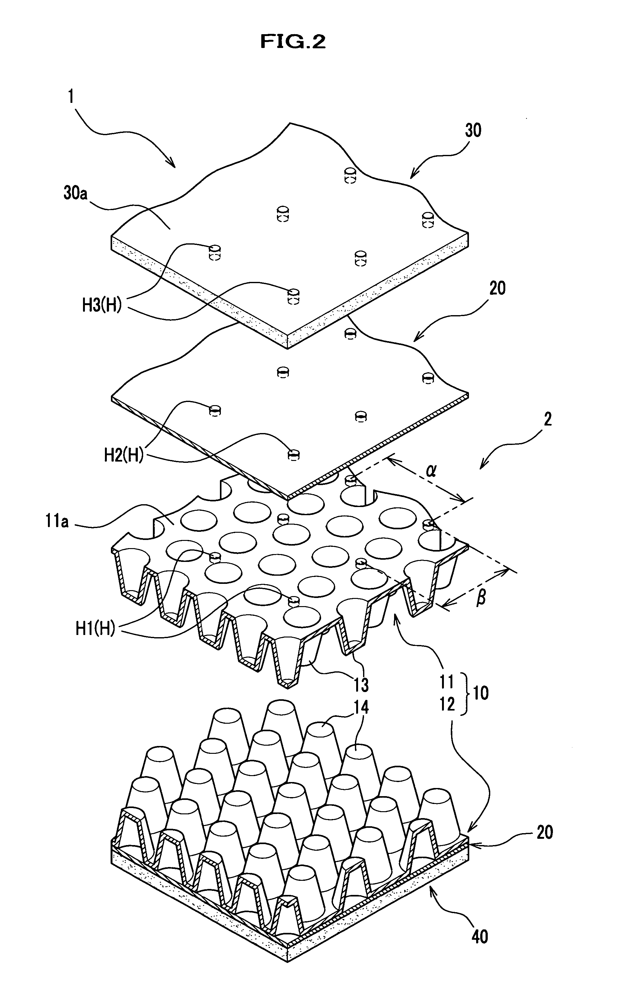
[0035] Description is given of an example (test results) of sound absorption obtained by the floor sheet assembly 1 according to the embodiment described above. Conditions under which testing was carried out are as follows:

(1) material for an intermediate member 10 and sheet member 20: polypropylene (PP)

(2) material for an insulator 40: urethane

(3) diameter of a hole H: 2 mm

(4) interval a of holes H: 40 mm

(5) interval β of holes H: 30 mm

(6) height of projections 13 and 14: 5.5 mm

(7) diameter of end portion of projections 13 and 14: 2 mm

(8) diameter of base portion (opening) of projections 13 and 14: 7 mm

(9) interval of projections 13 and 14: 11 mm

(10) thickness of thin panels 11 and 12: 0.5 mm

(11) thickness of a sheet member 20: 5.5 mm

(12) thickness of flooring 30: 2 mm

(13) thickness of an insulator 40: 20 mm

[0036] Description is given of sound absorption by the floor sheet assembly 1, which satisfies the conditions described above, with reference to FIG. ...


PUM


Abstract

A floor sheet assembly has an intermediate member and a pair of sheet members. The intermediate member includes at least a thin panel, on which a plurality of hollow projections is formed. The pair of sheet members sandwiches the intermediate member. The intermediate member and the pair of sheet members form a honeycomb structure.

Description

BACKGROUND OF THE INVENTION [0001] The present invention relates to a floor sheet assembly, which is attached to a floor of a vehicle or house. [0002] A floor sheet used for a room of a house is known, which employs flooring that is decorated with grain and bonded to a sheet of plywood (See patent document 1, for example). Because such a floor sheet not only is more elaborately designed than a carpet used for a vehicle but also has a characteristic of washability, it has been expected that such a floor sheet will be applied to a vehicle, a minivan, for example. Patent document 1: Japanese Published Patent Application 11-62197 [0003] However, it has not been appropriate that the floor of a vehicle should be covered with a conventional floor sheet without modification, which is developed for application to a house. This is attributed to the fact that this conventional floor sheet is adapted to be relatively thick so as to increase its sound absorption and stiffness, which leads to an...

Claims


Application Information

Patent Timeline
Patent Type & Authority Applications(United States)
IPC IPC(8): E04C2/00
CPCE04C2/3405E04C2002/3427
Inventor ISHII, NAOTOTAMANE, YASUYUKINISHIZAKA, MITSUHIROAOYAGI, KAORUANO, KAZUTAKA
Owner UBE NITTO KASEI CO LTD
Learn More