System for modifying the time-base of a video signal

a technology of video signal and time-base, which is applied in the field of system for modifying the time-base of a digital video stream, can solve problems such as skip or repeat frames, and problems such as rendering problems, and achieve the effect of loss of quality

Inactive Publication Date: 2006-04-13
KONINKLIJKE PHILIPS ELECTRONICS NV
View PDF3 Cites 12 Cited by
  • Summary
  • Abstract
  • Description
  • Claims
  • Application Information

AI Technical Summary

Benefits of technology

[0004] It is an object of the invention to provide a system that enables a user to render an encoded video signal in real-time, possibly with a loss in quality, whereas the signal can be perfectly reproduced after having been recorded by a storage device.
[0011] In the system according to the invention, the encoded video stream fully complies with the video encoding standard with respect to timing requirements for PCR and PTS. As such, a standard decoder / renderer that receives the stream through a communication interface can decode and render the stream in real-time, albeit at a possible loss of quality since the decoder may occasionally need to skip a frame (if the actual frame rate of the input video signal is higher then the maximum allowed deviation) or repeat a frame (if the actual frame rate of the input video signal is lower then the maximum allowed deviation). All video frames are present in the stream. A storage device is used to record frames of the stream. The frames can be supplied from the storage at a corrected frame rate that falls within the tolerances defined by the video encoding standard. To this end, the time base is scaled by comparing the actual frame times with the expected frame times. The actual frame times are derived from the PTS. The expected frame times are fixed, e.g. 40 msecs. between successive frames for a 25 Hz. system and thus the expected frame time between frames j−n and j that are sequentially n frames apart (n>0) is n×40 msecs. for such a frame rate. The actual frame time between those frames is determined by PTS[j]-PTS[j−n] (after conversion of a clock number to a corresponding duration). Comparing the actual frame times to the expected frame times gives a scaling factor. The PCR values can be scaled using this factor. Similarly, also the DTS values should be scaled if they are present. After this scaling, the offset between successive PTS values should correspond to the fixed frame time. Scaling may be done on two immediately successive PTS values (in this case n=1), giving a highly dynamic adjustment. Scaling may also be done on a larger time, e.g. 5 frames apart (n=5) or even all frames since the start (n=j, if the first frame is numbered 0). The storage acts as a buffer to compensate for the differences in actual frame rate and the constant desired frame rate of the encoding standard. Such a buffer needs to be substantially larger than required for jitter compensation as defined by the video encoding standard. The time-base correction according to the invention can be performed using a digital filter that calculates the modified PCR values.
[0014] According to the measure of the dependent claim 5, the digital video stream includes information on a nominal frame rate of the video signal and the time-base modifier is operative to derive the predetermined frame time from the digital video stream. The MPEG transport stream already includes this information (indicated by the so-called frame rate code in the sequence header). In this way, the time-base modification can be used for differing frame rates without a user having to configure the frame rate.
[0019] According to the measure of the dependent claim 10, the storage device is operative to use as the time stamps stored in the storage a counter value from a counter driven by the clock signal locked to the received video presentation time stamps (PTS). In this way, the already scaled PCR signal is also used to time stamp packets that do not have a PCR value, giving an accurate time for releasing the packets from storage.

Problems solved by technology

Such an encoded video stream should not be supplied through a network to a decoder / renderer as the decoding device may not be able to decode the signal.
On the other hand, directly using the MPEG clock and ignoring too large deviations in frame rate may result in rendering problems, such as having to skip or repeat frames.

Method used


Image

  • System for modifying the time-base of a video signal
  • System for modifying the time-base of a video signal
  • System for modifying the time-base of a video signal

Examples


Embodiment Construction

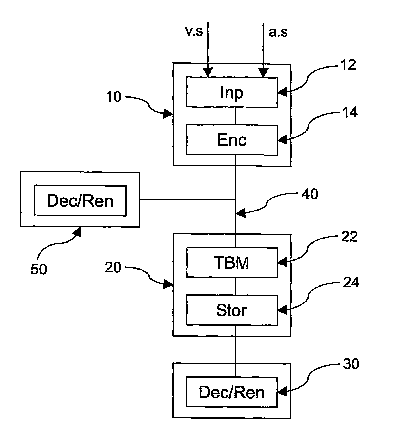
[0032]FIG. 1 shows a block diagram of the system according to the invention. The system includes an encoding device 10, a storage device 20 and a decoder / renderer 30. The encoding device 10 includes an input 12 for receiving at least one video signal. In the example of FIG. 1, it receives a video signal v.s. and an audio signal a.s. The encoding device 10 also includes an encoder 14 for encoding the AV signal(s) to an encoded stream for supply to at least the storage device 20 via a digital communication system 40. The encoding and transfer is according to a predetermined encoding standard. In a preferred embodiment, it complies with MPEG2. However, persons skilled in the art will be able to apply the principles also to other encoding / transmission formats. Any suitable communication system may be used. To enable stream-wise pushing of the data, the communication system preferably provides at least one isochronous communication channel. Suitable communication systems include, but are...


PUM


Abstract

A storage device 500 includes an input 405 for receiving a digital video stream complying with a predetermined video encoding standard via a digital video communication system. The stream includes a sequence of digital video frames, a sequence of program clock reference stamps (PCR) and a sequence of video presentation time stamps (PTS). A time-base modifier 510 replaces the PTS's by respective modified video presentation time stamps (M-PTS) based on a constant predetermined frame time between successive presentation time stamps and replaces the PCR's by respective modified program clock reference stamps (M-PCR) by scaling the PCR's using a scaling factor that depends on a ratio of an expected time between a video presentation time stamp j and a preceding video presentation time stamp j−n and an actual time between the video presentation time stamp j and the preceding video presentation time stamp j−n, where j≧n>0. The expected time is n times the predetermined frame time.

Description

FIELD OF THE INVENTION [0001] The invention relates to a system for modifying a time-base of a digital video stream; the system including an encoding device and a storage device connected via a digital video communication system, and a decoder / renderer. The invention further relates to a storage device and a time-base modifier. The invention also relates to a method of modifying a time-base of a digital video stream and to software for executing the method. BACKGROUND OF THE INVENTION [0002] Nowadays, most video signals have been recorded on tapes in an analog form. The quick uptake of digital video for playback, for example using DVD, has as a consequence that demand for recording video material on a digital recording medium also increases, for example using a recordable optical disc, like DVD+RW, or hard disc based recording devices. A commonly used digital encoding format is MPEG, in particular MPEG2. For recording an analog video signal, the user uses an analog reproducing devic...

Claims


Application Information

Patent Timeline
IPC IPC(8): H04N5/95H04N7/24
CPCH04N21/4147H04N21/4305H04N21/4334H04N21/4344H04N21/43632H04N5/91G11B20/10
Inventor SALOMONS, EDUARD WILLEMRIJCKAERT, ALBERT MARIA ARNOLD
Owner KONINKLIJKE PHILIPS ELECTRONICS NV
Why Eureka
Try Eureka