
Network connection device

a network connection and connection device technology, applied in the field of network connection devices, can solve problems such as network impairment, bursts of inputs that must be handled, and oversubscription of network resources

Inactive Publication Date: 2006-04-13
RIVULET COMM INC
View PDF90 Cites 73 Cited by
  • Summary
  • Abstract
  • Description
  • Claims
  • Application Information

AI Technical Summary

Benefits of technology

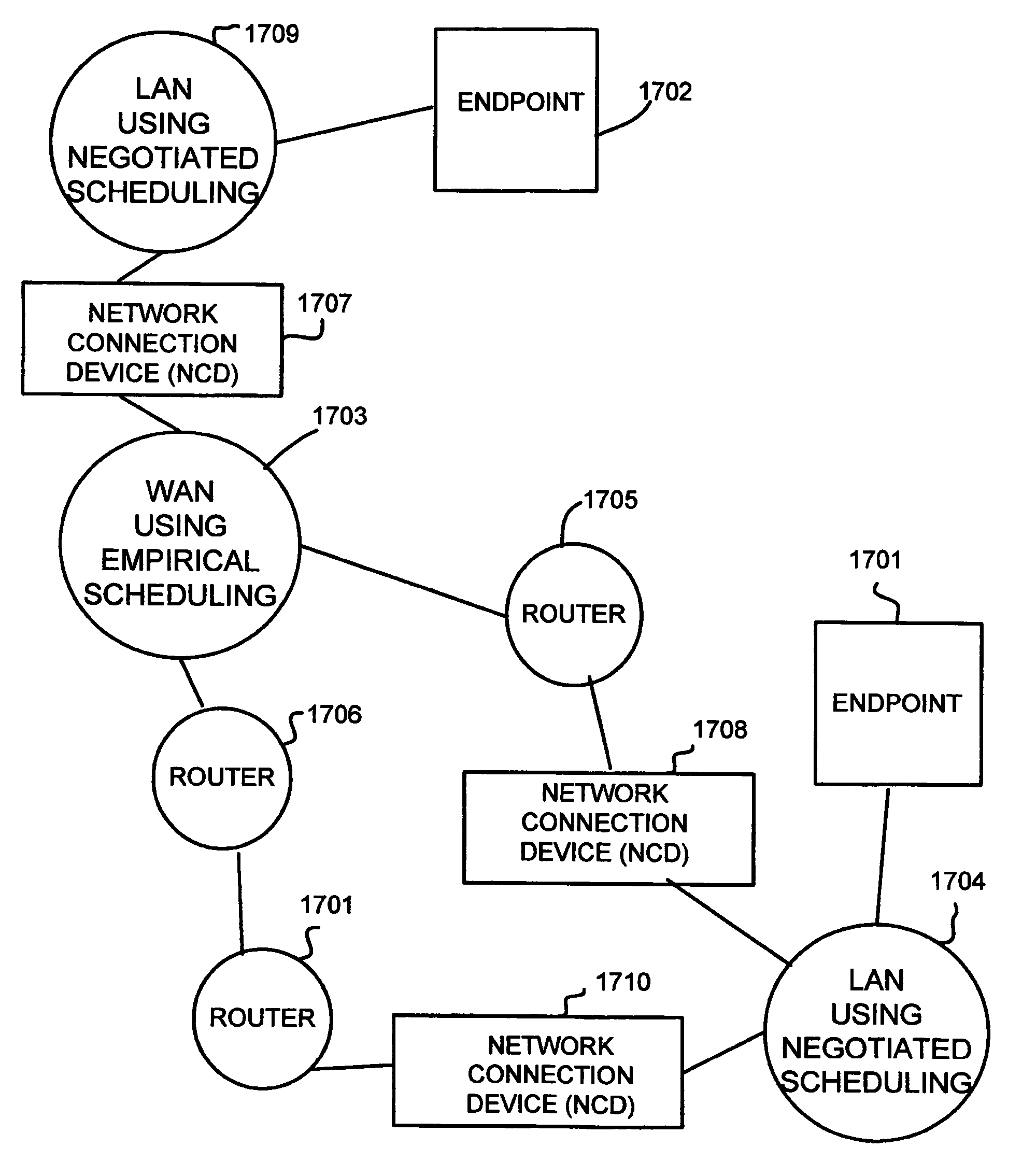
[0012] According to one aspect of the invention, a device and method are provided that allow endpoints on incompatible networks (e.g., an empirically scheduled network and a negotiated scheduled network) to communicate with each other. In one variation, a network connection device (NCD) acts as a proxy device which establishes a virtual connection between the networks. The device may perform handshaking functions to set up and tear down connections between the networks, and may optionally include firewall features and network address translation (NAT) functions. A method according to the invention includes steps of establishing a connection for packet transmission between the incompatible networks and for routing packets according to the differing network protocols.

Problems solved by technology

If they do, then network resources may be oversubscribed.
When this happens, data may be delayed or lost, resulting in network impairment.
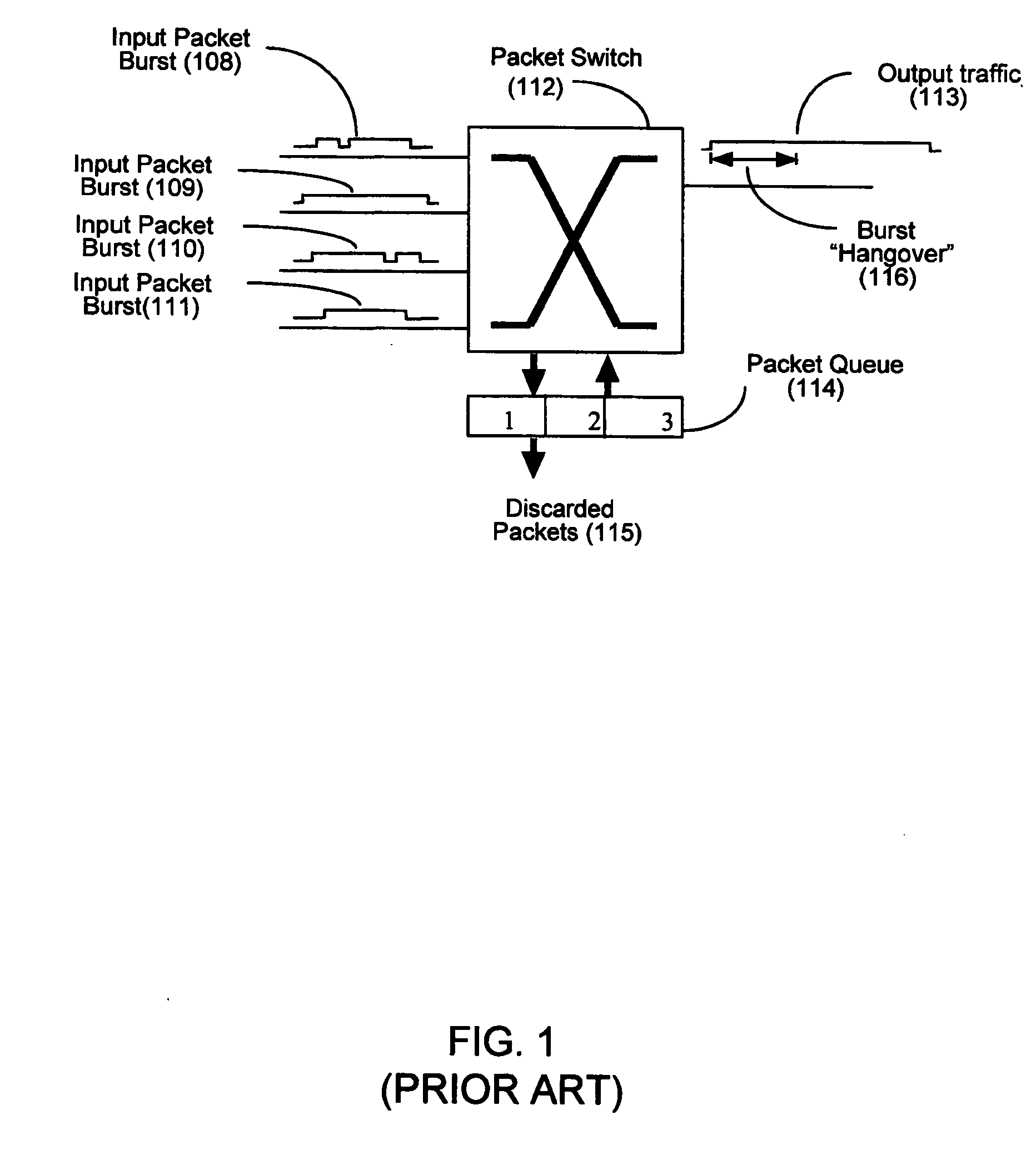
Packets may arrive at the switch at unpredictable times, leading to bursts of inputs that must be handled.
The higher-priority queues are typically emptied before the lower-priority queues, such that the lower-priority queues are more likely to lose data first.
IP systems suffer from impairments such as packet loss and jitter.
This happens because there is no control over how many such packets reach a router at any given instant.
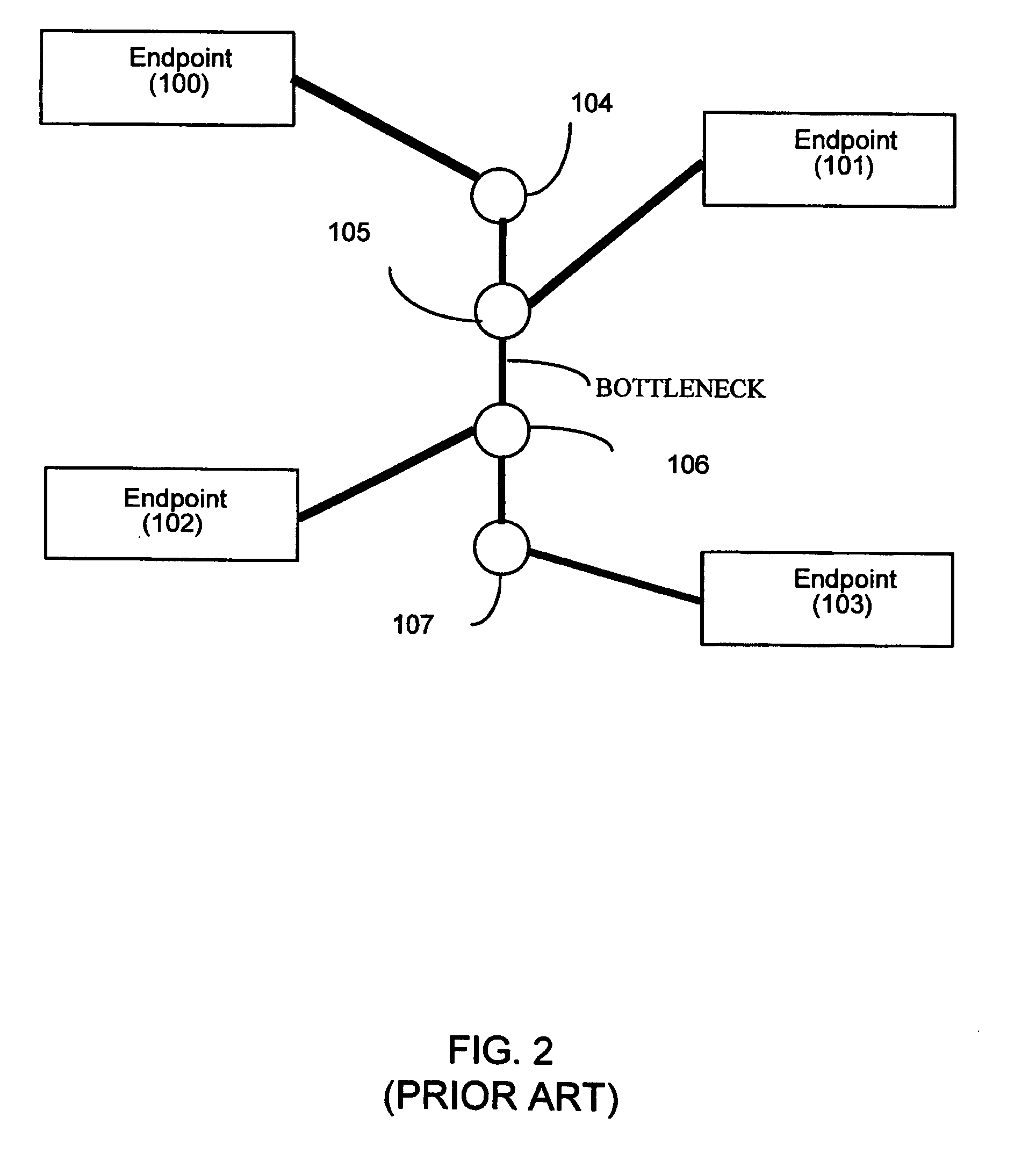
This may occur because too many packets may be simultaneously transmitted between the routers, causing the routers to discard overflow packets.
Another type of packet congestion problem may occur in a local area network (LAN) comprising LAN switches.
If too many packets are simultaneously transmitted by the other endpoints to 303, LAN switch 302 may have a queue overflow, causing packets to be lost.
This is typically caused by an internal queue in the LAN switch becoming full and thus becoming unable to accept new packets until the outgoing packets have been removed from the queue.
This creates a problem in that transmitting endpoints cannot be guaranteed that their packets will arrive, necessitating other solutions such as the use of guaranteed-delivery protocols such as Transmission Control Protocol (TCP).
Such solutions may be inappropriate for streaming video or other real-time applications, which cannot wait for retransmission of packets.
If endpoint 501 needs to transmit packets to endpoint 502, difficulties may arise due to incompatible protocols being used for transmitting packets on the networks.

Method used


Image

  • Network connection device
  • Network connection device
  • Network connection device

Examples


Embodiment Construction

[0033] Before describing various principles of the present invention, the following explains how packets can be transmitted in networks according to either an empirically determined scheduling technique or a negotiated scheduling technique. It should be clear that both techniques can be used on any type of network.

[0034] A. Empirical Scheduling of Network Packets

[0035] For networks that schedule packets using an empirical approach, a priority scheme can be used to assign priority levels to data packets in a network such that delivery of packets intended for real-time or near real-time delivery (e.g., phone calls, video frames, or TDM data packets converted into IP packets) are assigned the highest priority in the network. A second-highest priority level is assigned to data packets that are used for testing purposes (i.e. the so-called test packets). A third-highest priority level is assigned to remaining data packets in the system, such as TCP data used by web browsers. FIG. 6 ill...


PUM


Abstract

A network connection device bridges a first network that uses a negotiated packet delivery scheduling scheme and a second network that uses an empirically determined packet delivery scheduling scheme. The network connection device translates a request to communicate over the first network into a request to communicate over the second network, thus bridging the two networks. The negotiated packet delivery scheduling scheme permits endpoints to negotiate scheduled delivery times for packets, while the empirically determined packet delivery scheme tests various time interval locations in a network to determine favorable time locations for transmission. The two protocols are bridged by finding compatible overlaps between time interval locations in the two networks. This can provide error-free delivery with low jitter among packets.

Description

BACKGROUND OF THE INVENTION [0001] The present invention relates generally to a device and method for facilitating virtual connections between two different types of networks, each of which uses a different packet delivery scheme. [0002] As is generally known, Ethernet and Internet Protocol (IP) are systems for transmitting packets between different points on a communications network. These switching systems are known as “contention-based” systems. That is, all transmitters contend for network resources. All transmitters may transmit simultaneously. If they do, then network resources may be oversubscribed. When this happens, data may be delayed or lost, resulting in network impairment. [0003] As illustrated in FIG. 1, four streams of packets are input to a packet switch 112, which routes the packets to one or more outputs based on addressing information contained in each packet. Packets may arrive at the switch at unpredictable times, leading to bursts of inputs that must be handled...

Claims


Application Information

Patent Timeline
Patent Type & Authority Applications(United States)
IPC IPC(8): H04L12/56H04L12/28
CPCH04L12/5693H04L12/5695H04L47/115H04L47/2491H04L47/56H04L47/626H04L47/786H04L47/50H04L47/70
Inventor ROGERS, STEVEN A.
Owner RIVULET COMM INC
Learn More