
Memory control module and method for operating a memory control module

a memory control module and control module technology, applied in the direction of digital storage, electric digital data processing, instruments, etc., can solve problems such as errors when reading memory data

Inactive Publication Date: 2006-04-13
INFINEON TECH AG
View PDF6 Cites 23 Cited by
  • Summary
  • Abstract
  • Description
  • Claims
  • Application Information

AI Technical Summary

Benefits of technology

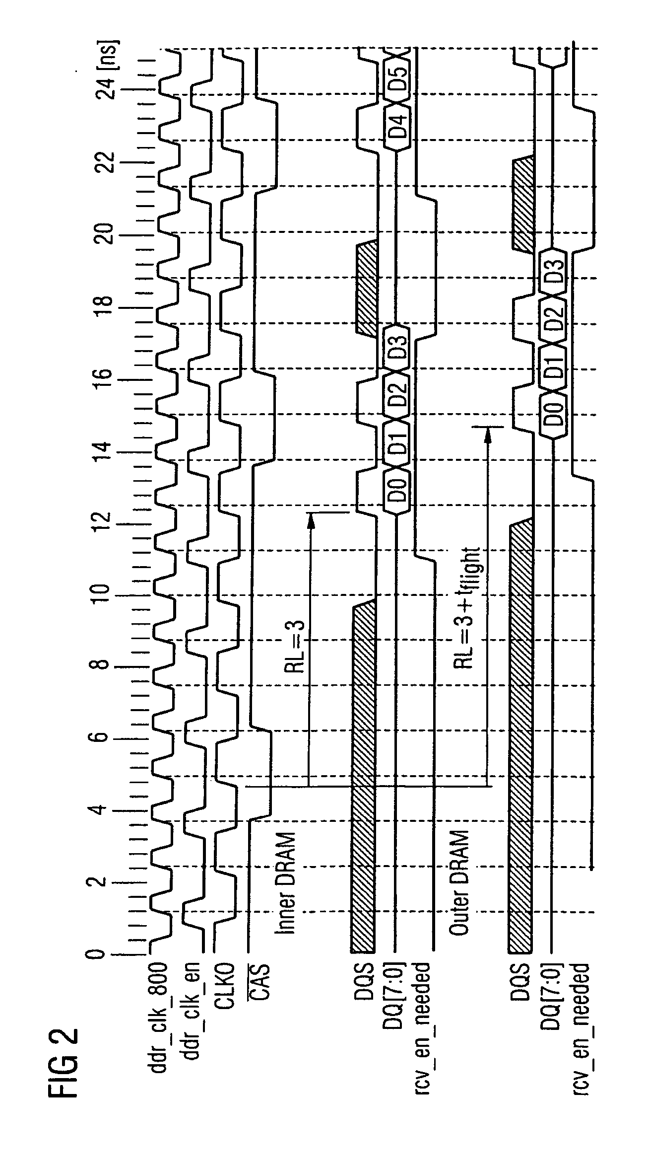
[0013] A fundamental advantage of the method according to the invention resides in the fact that, in this method, the data input amplifier(s)—which is / are connected to the memories—of the memory control module is / are switched on solely when data are actually being transmitted. This prevents the data input amplifiers being active and the memory control module being in the receiving mode if data are not actually being transmitted and undefined states are being transmitted via the respective data lines. Specifically, the method according to the invention thus optimizes the point in time at which the data input amplifiers of the memory control module are activated by ensuring that the data input amplifiers are activated only for a relatively short time right around the actual transmission of the memory or useful data. This prevents states which are not erroneously undefined on the DQ / DQS bus being “misinterpreted” as useful or memory data. In order to deliberately control the data input amplifiers in a corresponding manner, the sampling control signal which is sent to the memory control module together with the memory data is monitored for the presence of a preamble which indicates the imminent beginning of data transmission; the associated data input amplifier of the memory control module is switched on only when such a preamble is present.
[0015] One advantageous refinement of the method provides for each memory connection of the memory control module to be respectively individually monitored for the presence of a preamble of the associated sampling control signal, and for each of the data input amplifiers (input amplifiers) of the memory control module to be respectively switched on solely when such a preamble is detected. This refinement of the method thus ensures that each of the input amplifiers of the memory control module is respectively always switched on at the “right” or optimum point in time.

Problems solved by technology

This may result in errors when reading memory data.

Method used


Image

  • Memory control module and method for operating a memory control module
  • Memory control module and method for operating a memory control module
  • Memory control module and method for operating a memory control module

Examples


Embodiment Construction

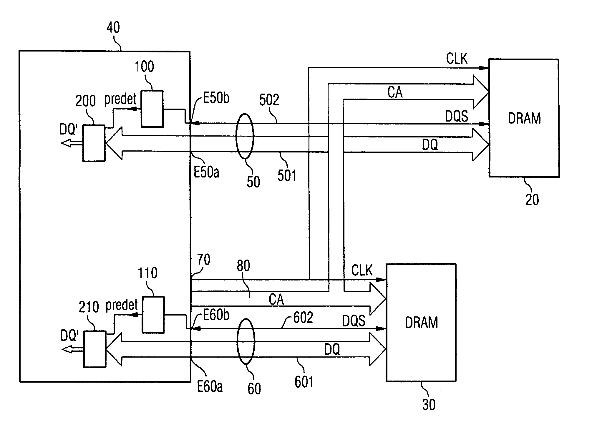
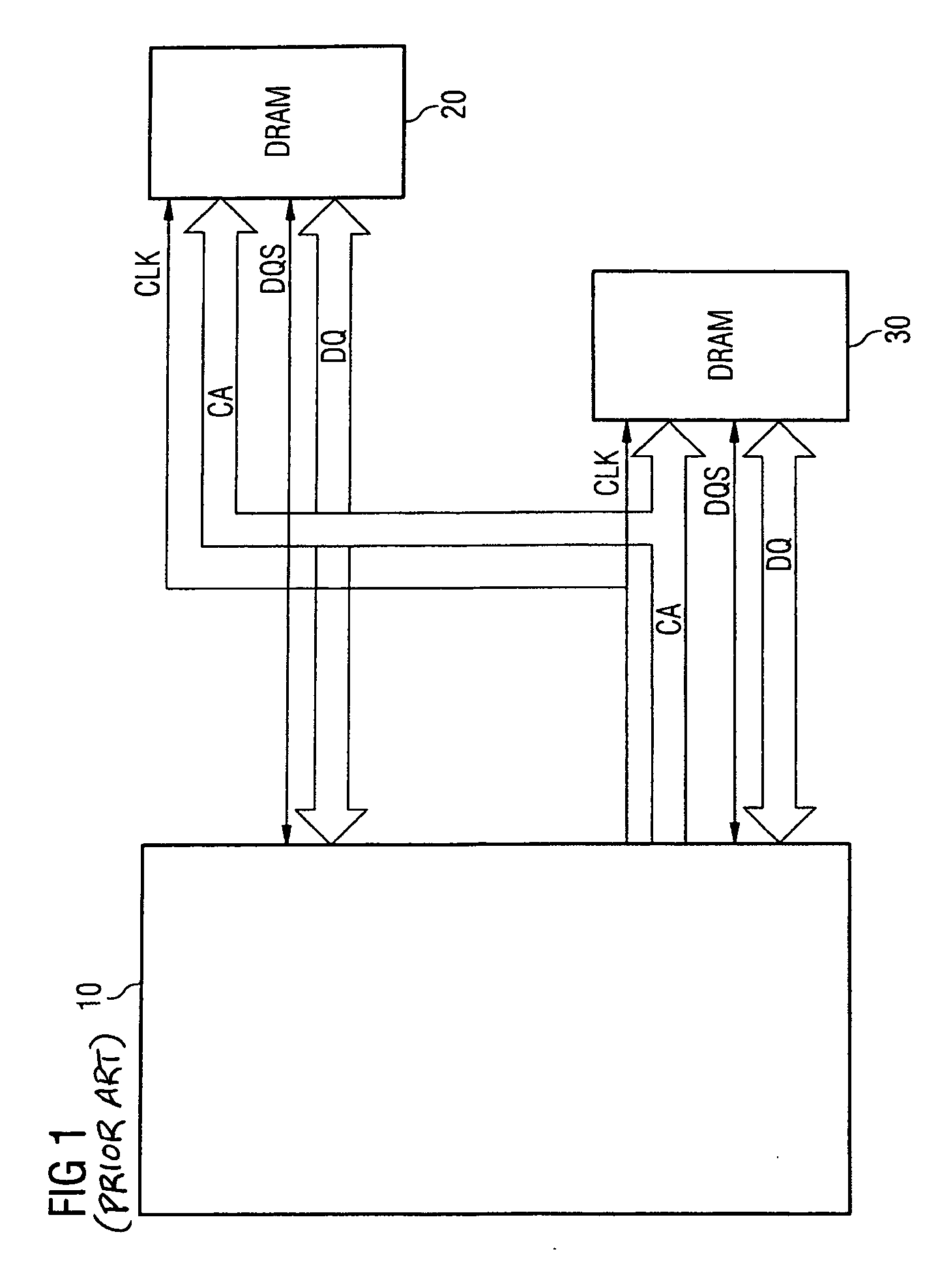
[0032]FIG. 3 illustrates an arrangement comprising a memory control module 40 and two DRAM memories 20 and 30. The two DRAM memories 20 and 30 correspond to the two memories shown in FIG. 1. The memory control module 40 shown in FIG. 3 differs from the memory control module 10 shown in FIG. 1 by virtue of the configuration of the signal input, as will be explained in more detail below.

[0033] The memory control module 40 has a first connection 50 for the memory 20. This first connection 50 is provided with a data signal connection E50a and a sampling control signal connection E50b. Connected to the data signal connection E50a is a first signal line or a data bus 501 for transmitting the memory data DQ which are stored in the memory 20 by the memory control module or are read back to the memory control module 40 from the memory 20; a signal line 502 for transmitting the strobe or sampling control signal DQS is connected to the sampling control signal connection E50b. The two signal l...


PUM


Abstract

The invention relates to a method for transmitting memory data from a memory to a memory control module, in which method a read command is transmitted from the memory control module to the memory, and the memory data which correspond to the read command are transmitted from the memory to the memory control module, a sampling control signal which controls the acceptance of the memory data into the memory control module being transmitted from the memory to the memory control module in parallel with the memory data. In order to avoid defective data transmission between the memory and the memory control module as reliably as possible, the sampling control signal is transmitted with a preamble which indicates the imminent beginning of data transmission, for the sampling control signal to be monitored for the presence of the preamble, and for a data input amplifier of the memory control module to be switched on only when the presence of the preamble is detected.

Description

CROSS-REFERENCE TO RELATED APPLICATIONS [0001] This application claims foreign priority benefits under 35 U.S.C. §119 to co-pending German patent application number DE 10 2004 048 056.7-5, filed 30 Sep. 2004. This related patent application is herein incorporated by reference in its entirety. BACKGROUND OF THE INVENTION [0002] 1. Field of the Invention [0003] The invention generally relates to a method for transmitting memory data from a memory to a memory control module which can be used, for example, to read stored memory data from a semiconductor memory, for example a DRAM memory and to transmit them to a memory control module (also usually referred to in the specialist terminology as a memory controller for short). [0004] 2. Description of the Related Art [0005]FIG. 1 illustrates, by way of example, an arrangement which is known from personal computers and comprises a memory control module 10 and two memories 20 and 30 which are connected to the latter. For the purposes of commu...

Claims


Application Information

Patent Timeline
IPC IPC(8): G11C7/00
CPCG06F13/1668
Inventor JAKOBS, ANDREASMUELLER, CHRISTIAN
Owner INFINEON TECH AG
Learn More