
Driving method of light emitting device

Inactive Publication Date: 2006-04-13
SEMICON ENERGY LAB CO LTD
View PDF16 Cites 10 Cited by
  • Summary
  • Abstract
  • Description
  • Claims
  • Application Information

AI Technical Summary

Benefits of technology

[0012] It is an object of the invention to provide a light emitting device capable of performing accurate gray scale display and a driving method thereof.
[0020] According to the driving method of the invention, a light emitting device capable of performing accurate gray scale display can be provided.

Problems solved by technology

However, when the capacitor (CEL) of the light emitting element 813 is large and a changed amount of the current value of the current supplied to the light emitting element 813 is large, it takes a long time to complete the charging / discharging of the capacitor (CEL) and complete the changing of the anode potential.
As set forth above, in the case where the potential of the gate electrode of the transistor 811 changes after a gray scale signal is inputted into each pixel, there is a problem in that the current value of the current supplied to the light emitting element 813 changes so that accurate gray scale display cannot be obtained.
In particular, in the case of performing black display, a current may flow into the light emitting element so that clear black display cannot be easily performed.

Method used


Image

  • Driving method of light emitting device
  • Driving method of light emitting device
  • Driving method of light emitting device

Examples


embodiment mode 1

[0035] This embodiment mode describes a driving method in the case where a predetermined signal is inputted plural times.

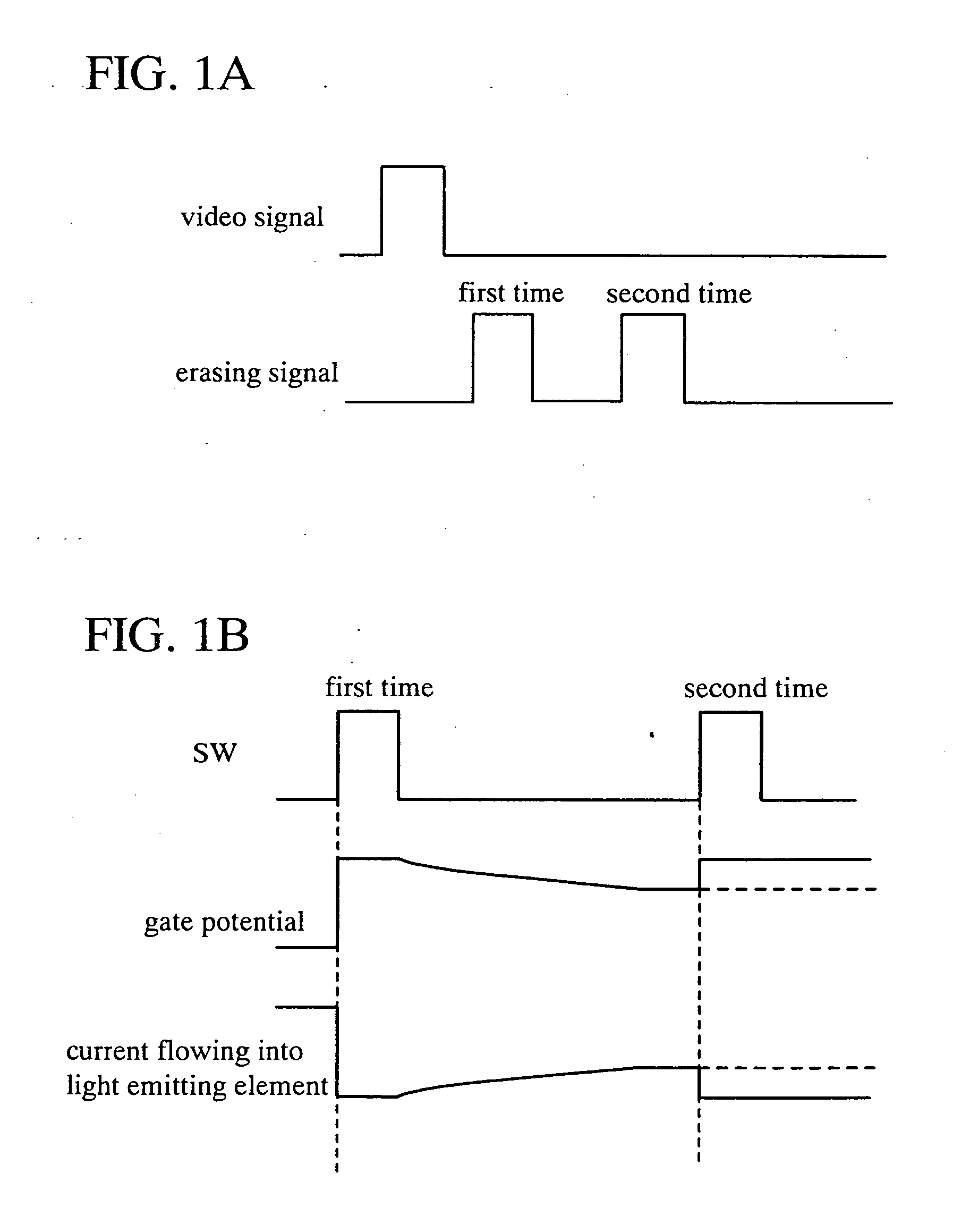
[0036] In FIG. 1A, operation in the case where an erasing signal is inputted two times in a digital gray scale method is shown. First, at a predetermined timing, a digital signal for display (a video signal) is inputted, and then a first erasing signal is inputted after a predetermined time has passed. At this time, if the capacitor (CEL) or the parasitic capacitance (CP) exists, a potential of a gate electrode (a gate potential) of a driving transistor does not relatively become 0 only by the first erasing signal so that off operation cannot be performed; as a result, it is difficult to perform accurate gray scale display and gray scale deviation occurs. In view of this, according to the invention, the erasing signal is inputted again, that is, a second erasing signal is inputted after a predetermined time has passed. Accordingly, the gate potential can be relat...

embodiment mode 2

[0043] Described in this embodiment mode is a timing chart of a digital gray scale method in the case where a period for inputting a video signal and a period for inputting an erasing signal plural times are provided.

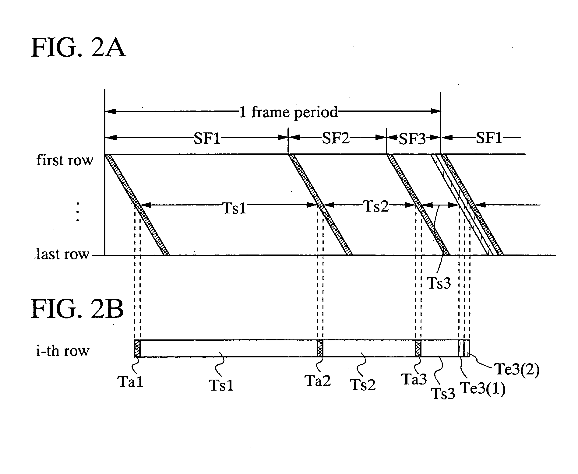
[0044] One frame period can be divided into a plurality of subframe periods SF1, SF2, . . . , and SFn (n is a positive integer). FIG. 2A is a timing chart in the case where one frame period is divided into three subframe periods (SF1, SF2, and SF3) to perform 6-gray scale display, in which an erasing signal is inputted two times in the subframe period SF3. FIG. 2B is a timing chart focusing on a scan line of the i-th row.

[0045] The subframe periods (SF1, SF2, and SF3) have writing operation periods for inputting a video signal (Ta1, Ta2, and Ta3) (also referred to as periods for inputting a writing signal) and light emitting periods for performing light emission depending on the written video signal (Ts1, Ts2, and Ts3) respectively. The length of the light emitting pe...

embodiment mode 3

[0050] Described in this embodiment mode is a timing chart of a digital gray scale method in the case where a plurality of writing operation periods (also referred to as periods for inputting a writing signal) is provided.

[0051] One frame period can be divided into a plurality of subframe periods SF1, SF2, . . . , and SFn (n is a positive integer). FIG. 3A is a timing chart in the case where one frame period is divided into three subframe periods (SF1, SF2, and SF3) to perform 6-gray scale display, in which a period for applying a reverse voltage is provided. FIG. 3B is a timing chart focusing on a scan line of the i-th row.

[0052] The subframe periods (SF1, SF2, and SF3) include writing operation periods (Ta1(W), Ta2(W), and Ta3(W)) and light emitting periods for performing light emission depending on the written signal (Ts1, Ts2, and Ts3) respectively. The length of the light emitting periods is set to satisfy Ts1:Ts2:Ts3=22:21:20. In the shortest subframe period SF3, a period fo...


PUM


Abstract

If a potential of a gate electrode of a driving transistor varies after a gray scale signal is inputted into each pixel, a current value of a current supplied to a light emitting element varies so that accurate gray scale display cannot be obtained. In particular, in the case of performing black display, current may flow, which makes clear black display difficult. Accordingly, the invention provides a light emitting device capable of performing accurate gray scale display, and a driving method thereof. According to the invention, a signal for display is inputted plural times within a predetermined timing period, or a writing operation period is lengthened. Consequently, the gate voltage of the transistor is determined after the anode potential of the light emitting element is stabilized, and therefore accurate gray scale display can be performed.

Description

BACKGROUND OF THE INVENTION [0001] 1. Field of the Invention [0002] The present invention relates to a configuration for performing accurate gray scale display in a display device having a light emitting element (a light emitting device), and a driving method thereof. [0003] 2. Description of the Related Art [0004] In a conventional light emitting device, a pixel configuration as shown in FIG. 9 has been proposed in which a switching element 810 whose on / off is controlled by a video signal inputted from a signal line 814, a transistor 811 for driving a light emitting element 813, and a capacitor 812 provided between a power source line 815 and a gate electrode of the transistor 811 to hold a gate-source voltage of the transistor 811 (see Patent Document 1) are provided. [Patent Document 1] Japanese Patent Laid-Open No. 2001-343933 [0005] It is considered that an equivalent circuit of a light emitting element described in Patent Document 1 can be shown by a parallel circuit includin...

Claims


Application Information

Patent Timeline
IPC IPC(8): H01L33/00H05B44/00
CPCG09G3/2022G09G3/3291G09G2300/0809G09G2300/0842G09G2320/043G09G2310/0256G09G2310/061G09G2320/0233G09G2320/0252G09G2300/0861
Inventor MIYAGAWA, KEISUKEFUKUMOTO, RYOTA
Owner SEMICON ENERGY LAB CO LTD
Learn More