
Storage system

Inactive Publication Date: 2006-04-06
HITACHI LTD
View PDF7 Cites 18 Cited by
  • Summary
  • Abstract
  • Description
  • Claims
  • Application Information

AI Technical Summary

Benefits of technology

[0010] Hence in a storage system, in addition to tasks, in which ease of operation is required, to make settings and perform maintenance for each of the portions of the storage apparatus, an object of the invention is to enable fault information notification of monitoring and maintenance terminals, for which high reliability is demanded, without causing any decline in reliability.

Problems solved by technology

However, if an attempt is made to perform monitoring and notification operations with the high degree of reliability required using the same hardware as the SVP, which functions as a maintenance operations terminal to make device settings and perform maintenance operations, and for which ease of operation is demanded, then an application program to perform the above-described monitoring and notification tasks must run on the above-described commercial OS, so that degradation of the reliability of the monitoring and notification tasks becomes a problem.

Method used


Image

  • Storage system
  • Storage system
  • Storage system

Examples


Embodiment Construction

[0043] Below, aspects of the invention are explained in detail using the drawings.

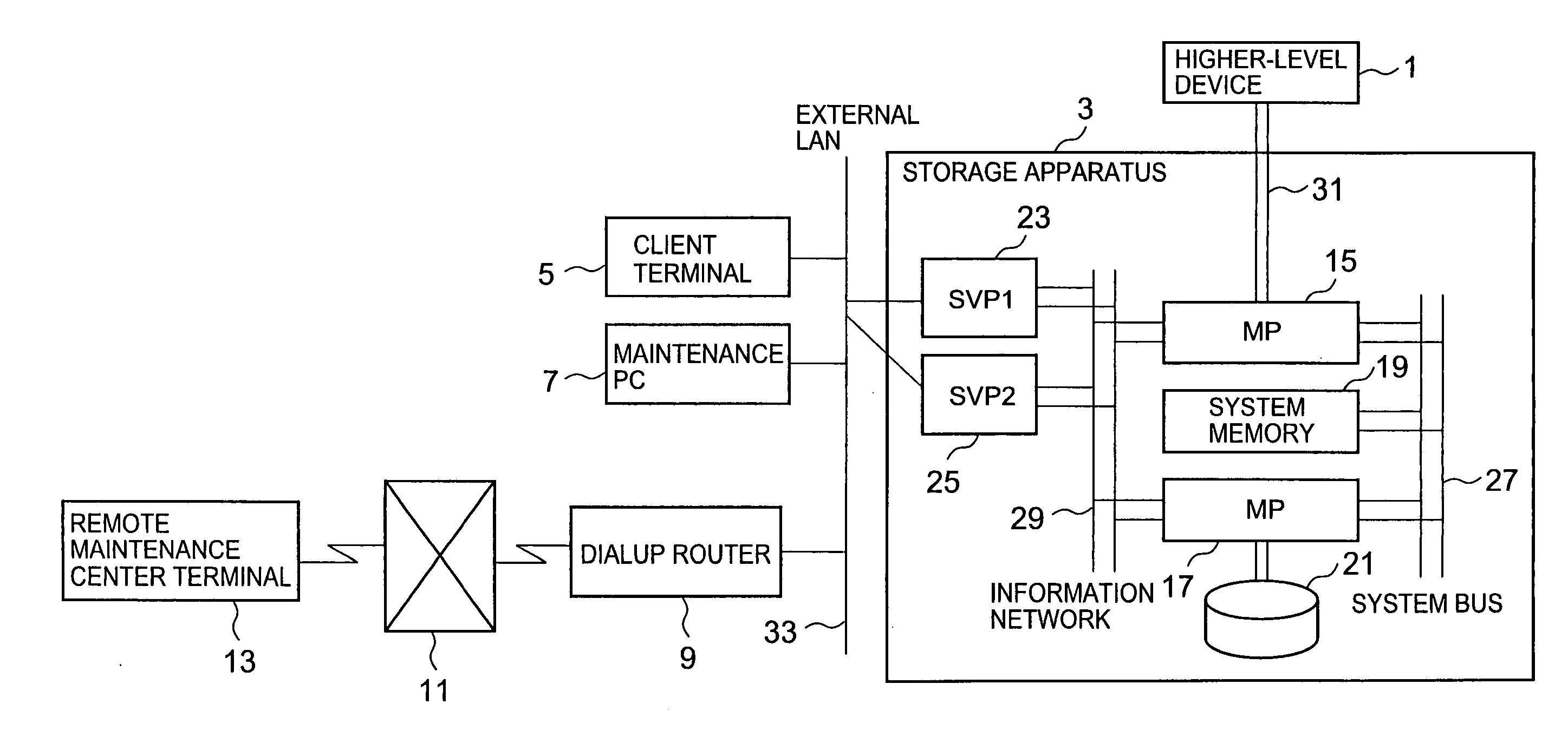
[0044]FIG. 1 is a block diagram showing the overall configuration of an information processing system comprising a storage apparatus of a first aspect of the invention.

[0045] As shown in FIG. 1, the above information processing system comprises a higher-level device 1, storage apparatus 3, client terminal 5, maintenance PC 7, dialup router 9, public telephone circuit network 11, and remote maintenance center terminal 13. The storage apparatus 3 comprises a plurality of MPs (microprocessors) 15, 17 (for convenience in the drawing and explanation, in FIG. 1 only two are shown, assigned the symbols 15 and 17), and system memory (SM (shared memory) in which is stored, for example, system configuration information required for operation and for maintenance and management of the information processing system, operation management information, and similar) 19. In addition to the above portions, the storage ...


PUM


Abstract

In addition to setting tasks and maintenance tasks for each portion of a storage apparatus, for which ease of operation is demanded, a storage system enables notification of a monitoring and maintenance terminal, for which high reliability is demanded, of fault information, without detracting from reliability. The functions of a SVP 23 and SVP 25 are functions to monitor the storage apparatus 3, and functions for notification to a remote maintenance center terminal 13 or similar, for which high reliability is demanded. The notification function involves notification to a remote maintenance center terminal 3 or similar of a fault or other event in the storage apparatus 3, detected by the monitoring function. The functions of the SVP 23 and SVP 25 are limited to functions for notification of faults in the storage apparatus 3, notification of information other than faults, and SNMP functions, so that the volume of the OS and other programs installed on the SVP 23 and SVP 25 is reduced.

Description

CROSS-REFERENCE TO PRIOR APPLICATION [0001] This application relates to and claims priority from Japanese Patent Application No. 2004-292170, filed on Oct. 5, 2004, the entire disclosure of which is incorporated herein by reference. BACKGROUND OF THE INVENTION [0002] 1. Field of the Invention [0003] This invention relates to an information processing system comprising a storage apparatus connected to a higher-level device or to another storage apparatus to enable communication. [0004] 2. Description of the Related Art [0005] In the prior art, fault monitoring systems have been proposed with the object of accurately ascertaining faults occurring within a large-scale computer system, in time series order of occurrence. Such a fault monitoring system comprises a plurality of nodes, which are mutually independent computers; a crossbar data switch which switches signal paths between nodes; a crossbar control device which controls driving of the crossbar data switch; a slave service proce...

Claims


Application Information

Patent Timeline
IPC IPC(8): G06F11/00
CPCG06F11/0727G06F11/0748G06F11/0784G06F11/3034G06F11/3055H04L43/0817H04L41/0213
Inventor FUKUI, KATSUHIKO
Owner HITACHI LTD
Learn More