[0006] The present invention was conceived in view of the problems described above and it is a principal object of the present invention to provide an applied film forming apparatus and an applied film forming method that can form, without a large increase in manufacturing cost, an applied film with no convex part that protrudes significantly upward at an outer circumferential edge part.
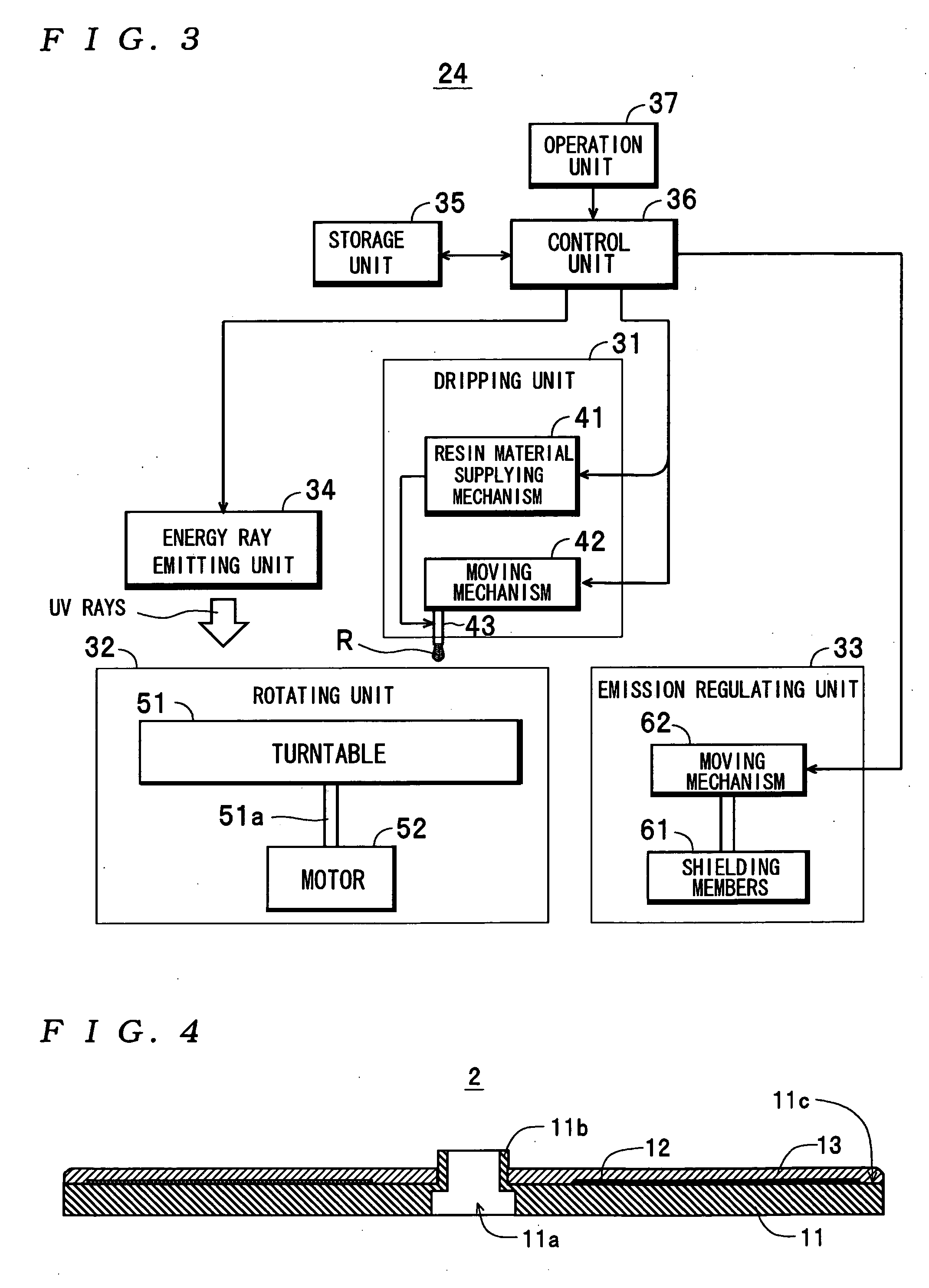
[0009] According to the above applied film forming apparatus and applied film forming method, after the applied material has been dripped onto the one surface and the substrate has been rotated to cause the applied material to spread out, the energy beam is emitted toward the one surface of the substrate and the emission of the energy beam onto the applied material on the outer circumferential edge part of the one surface of the substrate is regulated in a state where the substrate is rotated at a predetermined rotational velocity. For this reason, by rotating the substrate in a state where the applied material applied to parts of the one surface of the substrate aside from the outer circumferential edge part has been cured, it is possible to push only the small amount of applied material on the outer circumferential edge part outside the substrate by
centrifugal force. This means it is possible to suppress the amount of applied material pulled back onto the outer circumferential edge part when the rotation stops to a sufficiently small amount, and as a result it is possible to prevent a large convex part from being formed on the outer circumferential edge part. Since a
cutting away process for the applied material after curing can be made unnecessary, a cleaning step of removing the pulverized applied material produced by the
cutting away process also becomes unnecessary, and therefore an applied film with no large convex part on an outer circumferential edge part thereof can be formed without causing an increase in the manufacturing cost due to such process and step. Also, by emitting an energy beam in a state where the substrate is rotated, the applied film can be formed with a more uniform thickness compared to a construction that emits an energy beam in a state where the substrate is stopped.
[0010] Also, according to the above applied film forming apparatus and applied film forming method, the step of dripping the applied material onto the one surface of the substrate, the step of spreading out the dripped applied material, and the step of emitting the energy beam onto the one surface of the substrate are carried out without changing the position of the substrate, that is, with the substrate positioned at a single location. For this reason, compared to an applied film forming apparatus and applied film forming method that carry out the various steps at different positions, the time taken to form the applied film on the substrate can be reduced by an amount corresponding to the movement of the substrate that is no longer required. Also, by carrying out the various steps with the substrate positioned at a single location, the construction of the entire applied film forming apparatus can be made more compact by an amount corresponding to movement of the substrate no longer being necessary. Additionally, since the construction of the applied film forming apparatus can be simplified by an amount corresponding to a moving device for moving the substrate not being necessary, the cost of the applied film forming apparatus can be kept low.
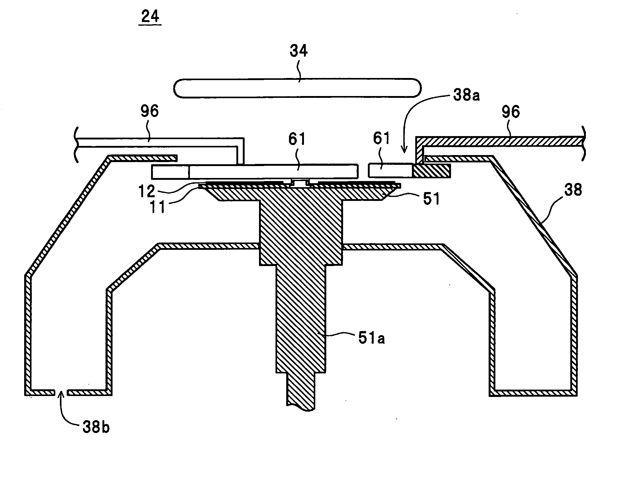
[0011] In this case, the emission regulating unit may include a plurality of shielding members that in a connected state construct a plate-like body in which a circular opening with a slightly smaller
diameter than a
diameter of the substrate is formed, and a moving mechanism for moving and connecting the shielding members to construct the plate-like body, wherein the
control unit may control the movement mechanism to move and connect the shielding members to regulate the emission of the energy beam on the applied material on the outer circumferential edge part. It is also possible to use a method where the emission of the energy beam onto the applied material on the outer circumferential edge part is regulated by connecting a plurality of shielding members that in a connected state construct a plate-like body in which a circular opening with a slightly smaller
diameter than a diameter of the substrate is formed. According to this applied film forming apparatus and applied film forming method, compared to a construction where the shielding members are formed as an integral body, for example, it is possible to reduce the area of a withdrawal position of the shielding members when the shielding members are not in use and therefore a corresponding reduction can be made in the size of the applied film forming apparatus.
[0012] It is also possible to use a construction where gaps between the respective shielding members in the connected state and the outer circumferential edge part are respectively in a range of 2 mm to 10 mm, inclusive. It is also possible to use a method where the respective shielding members are connected so that gaps between the respective shielding members in the connected state and the outer circumferential edge part are respectively in a range of 2 mm to 10 mm, inclusive. According to this applied film forming apparatus and applied film forming method, it is possible to reliably regulate the emission of the energy beam onto the applied material on the outer circumferential edge part. Also, even if the substrate vibrates due to rotation, for example, it is possible to reliably avoid contact between the outer circumferential edge part and the shielding members.
[0013] It is also possible to use a construction including a wall part that is disposed close to a side surface of the substrate during spreading out and causes the applied material that protrudes outside the substrate to flow downward along the side surface of the substrate. In the applied film forming method also, a wall part may be disposed close to a side surface of the substrate during spreading out and may cause the applied material that protrudes outside the substrate to flow downward along the side surface of the substrate. According to this applied film forming apparatus and applied film forming method, an applied film that is continuous from the surface to the side surface of the substrate can be formed. For this reason, it is possible to reliably prevent the applied film from becoming detached from the substrate due to an
impact or contact with an object. In addition, since the applied film is formed on the side surface of the substrate, it is possible to reliably prevent damage to the side surface due to an
impact or contact with an object.


