
Semiconductor device and manufacturing method thereof

a technology of semiconductor devices and semiconductor packaging, which is applied in the direction of semiconductor devices, semiconductor/solid-state device details, electrical apparatus, etc., can solve the problems of preventing voids in the ic packages, and achieves the effect of facilitating the miniaturization of ic packages, improving reliability, and facilitating handling

Inactive Publication Date: 2006-04-06
SEIKO EPSON CORP
View PDF4 Cites 2 Cited by
  • Summary
  • Abstract
  • Description
  • Claims
  • Application Information

AI Technical Summary

Benefits of technology

[0007] An advantage of the present invention is to provide a semiconductor device and a method therefor which enable further miniaturization of the IC package.
[0008] According to an aspect of the invention, a semiconductor device includes: a circuit board having an inner terminal on one surface, an outer terminal on the other surface, and wiring between the inner terminal and the outer terminal; a semiconductor chip flip-chip bonded to the inner terminal against the circuit board; and a sealing resin covering the semiconductor chip and having a side portion of a diced surface that is the same as a side portion of the circuit board.
[0009] According to another aspect of the invention, a semiconductor device includes: a circuit board having an inner terminal on one surface, an outer terminal on the other surface, and wiring between the inner terminal and the outer terminal; a semiconductor chip flip-chip bonded to the inner terminal against the circuit board; a filling auxiliary member provided at least between a central region of the semiconductor chip and the circuit board; and a sealing resin covering the semiconductor chip and having a side portion of a diced surface that is the same as a side portion of the circuit board.
[0010] In these cases, each of the semiconductor device of the invention, by covering the semiconductor chip with the sealing resin, contributes to easy handling and improving reliability. The sealing resin has the side surface sharing the same surface with the side portion of the circuit board while suppressing voids. Accordingly, the flip-chip bonding portion is sufficiently protected at the same time the package is miniaturized. Further, for the semiconductor device having the filling auxiliary member, the filling auxiliary member can help with the penetration of the sealing resin into areas where the sealing resin does not easily penetrate.
[0011] Further, in order to obtain the downsized semiconductor package with improved handling convenience and reliability, it is preferable that the semiconductor device of the invention further include any of the following characteristics:
[0012] the sealing resin is a molding resin diced together with the circuit board;

Problems solved by technology

However, it is very likely that the fillet includes voids.
As a consequence, the circuit board must be much larger than the IC chip, and this inhibits the miniaturization of the IC package.

Method used


Image

  • Semiconductor device and manufacturing method thereof
  • Semiconductor device and manufacturing method thereof
  • Semiconductor device and manufacturing method thereof

Examples


first embodiment

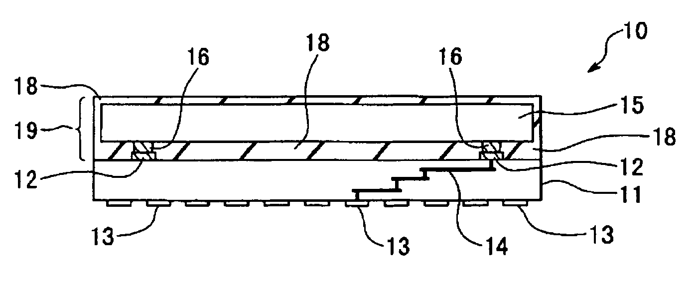
[0042]FIG. 1 is a cross sectional diagram showing an essential part of the semiconductor device of the invention. A semiconductor package 10 has a structure as follows. A circuit board 11 is an organic multilayer wiring substrate and includes inner terminals 12 on one surface and outer terminals 13 on the other surface. The inner terminals 12 and the outer terminals 13 are connected by multilayer wiring 14 interposed therebetween. The inner terminals 12 are conductive patterns plated with Au, for example. Alternatively, the inner terminals 12 may be composed by Sn plating or solder plating with Sn—Cu, Sn—Ag, Sn—Ag—Cu, or the like. The outer terminals 13 are conductive patterns including lands, for example. Alternatively, the outer terminals 13 may be composed of ball electrodes or of other bump electrodes.

[0043] A semiconductor chip 15 has bump electrodes 16 on its primary surface and is flip-chip bonded to the inner terminals 12 against the circuit board 11. The bump electrodes 16 ...

second embodiment

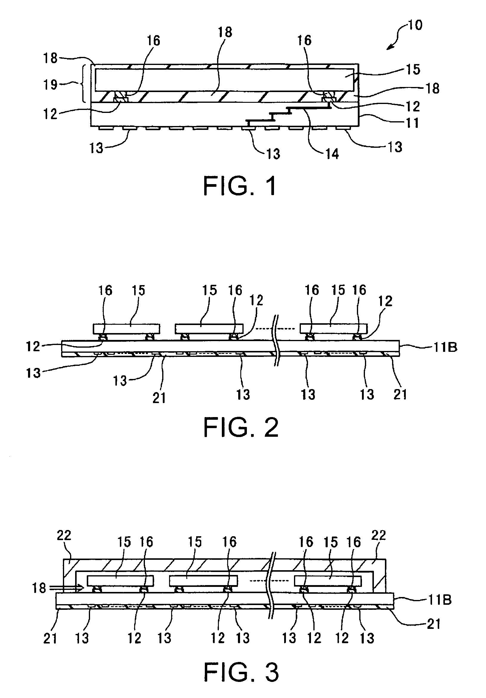
[0046]FIG. 2 to FIG. 4 are cross sectional diagrams each showing an essential part of the method for manufacturing the semiconductor device of the invention in the order of the process and showing a procedure for enabling the structure of FIG. 1. FIG. 2 to FIG. 4 are explained using the same reference numbers for the same elements as those used in FIG. 1.

[0047] As shown in FIG. 2, a circuit board 11B having a plurality of flip-chip bonding regions is prepared. The circuit board 11B is an organic multilayer wiring substrate and includes the inner terminals 12 on one surface and the outer terminals 13 on the other surface. The inner terminals 12 are each plated with Au for flip-chip bonding. Further, the other surface of the circuit board 11B having the outer terminals 13 formed thereon is protected by protection tape 21 attached thereto. The outer terminals 13 are not in the complete configuration at this point, and the electrode members may be added in the subsequent process.

[0048]...

third embodiment

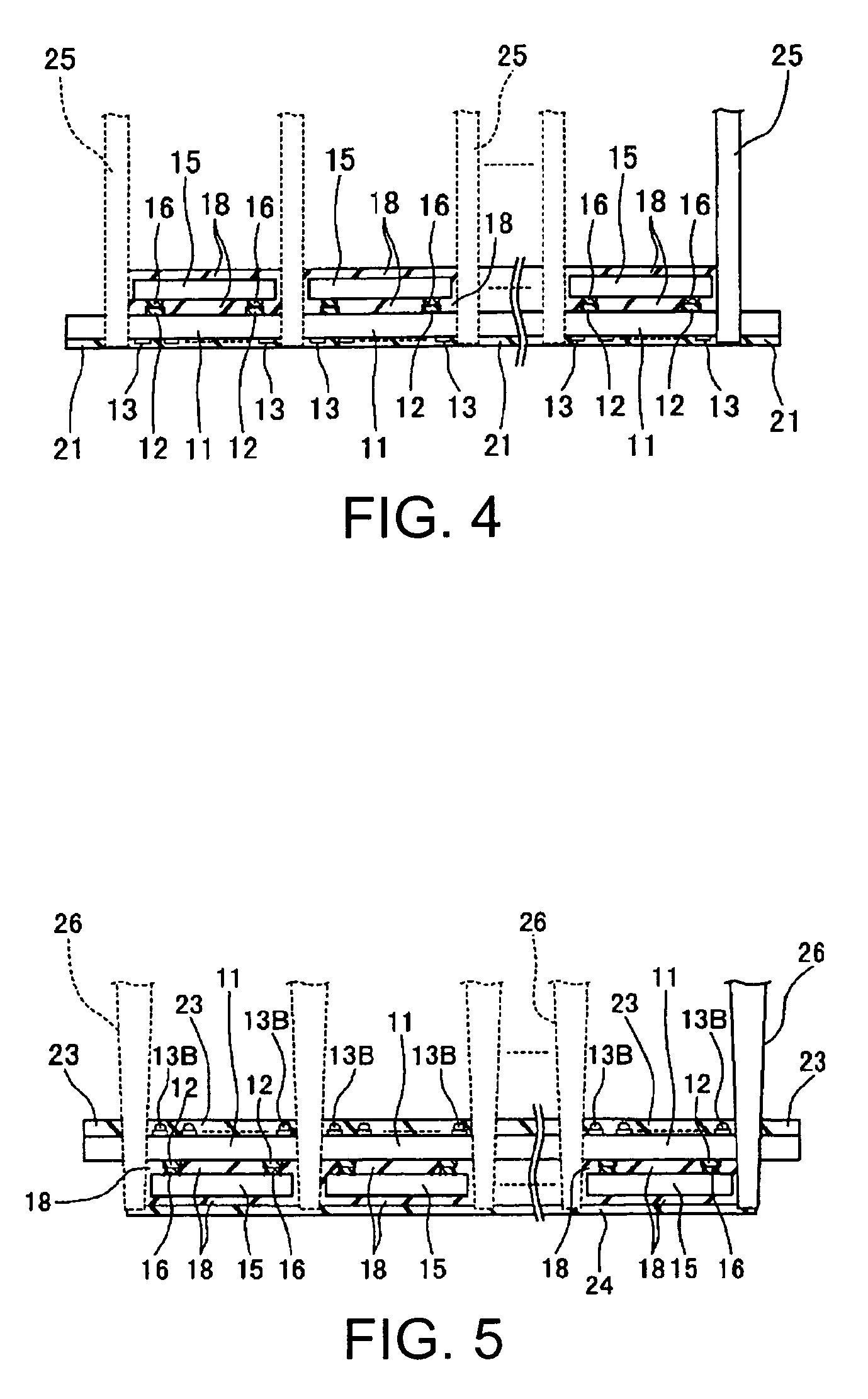
[0053]FIGS. 5 and 6 are cross sectional diagrams each showing the essential part of the method for manufacturing the semiconductor device and the semiconductor device of the third embodiment and showing a procedure for forming a working example having a modified structure of FIG. 1. FIGS. 5 and 6 are explained using the same reference numbers for the same elements as those used in FIG. 1.

[0054] The same processes as in the second embodiment are carried out up to FIG. 3. Thereafter, as shown in FIG. 5, after the curing, the mold of the cured sealing resin 18 is taken out from the die. Then, the electrode members, that is, ball electrodes 13B in this case, are further added to the outer terminals 13. After that, protection tape 23 is attached to the side of the circuit board 11B. Also, protection tape 24 is attached to the side of the sealing resin 18. Next, the dicing process is carried out with the side of the sealing resin 18 facing down and supported. For the dicing, a dicing blad...


PUM


Abstract

A semiconductor device, includes: a circuit board having an inner terminal on one surface, an outer terminal on the other surface, and wiring between the inner terminal and the outer terminal; a semiconductor chip flip-chip bonded to the inner terminal against the circuit board; and a sealing resin covering the semiconductor chip and having a side portion of a diced surface that is the same as a side portion of the circuit board.

Description

BACKGROUND OF THE INVENTION [0001] 1. Technical Field [0002] The present invention relates to a semiconductor device and a method for manufacturing the same, in which a semiconductor element flip-chip bonded to a circuit board is sealed with a resin. [0003] 2. Related Art [0004] Recently, products such as portable equipment are becoming increasingly multi-functional at the same time they are shrinking in size. Naturally, there are demands for miniaturizing the semiconductor parts inside these products and for downsizing the mounting area. A chip size package (CSP) is one of these products mounted on a wiring substrate within its limited space. The CSP utilizes a double-sided or multilayered wiring circuit board, and an IC chip is flip-chip bonded to one surface of the board, while an outer terminal is provided on the other surface of the board (e.g., see Issued Japanese Patent 3332555, p. 5 and FIG. 4). [0005] For the CSP, underfill (sealant) is used in the flip-chip bonding portion...

Claims


Application Information

Patent Timeline
Patent Type & Authority Applications(United States)
IPC IPC(8): H01L23/48
CPCH01L21/561H01L2224/16235H01L23/3114H01L23/3121H01L24/83H01L24/97H01L2224/16225H01L2224/32225H01L2224/73203H01L2224/83104H01L2224/8385H01L2224/97H01L2924/01015H01L2924/01029H01L2924/01047H01L2924/0105H01L2924/01078H01L2924/01079H01L2924/07802H01L2924/14H01L2924/15184H01L2924/15311H01L21/565H01L2224/29111H01L2924/1579H01L2924/1517H01L2924/0133H01L2924/0132H01L2924/0665H01L2924/014H01L2924/01033H01L2924/01006H01L2224/2919H01L24/32H01L2224/81H01L2924/00H01L2924/00014H01L2924/181
Inventor WATANABE, ATSUSHI
Owner SEIKO EPSON CORP
Learn More