
Tool for efficient setting of grading height

Inactive Publication Date: 2006-04-06
WALLACH GARRETT +1
View PDF12 Cites 6 Cited by
  • Summary
  • Abstract
  • Description
  • Claims
  • Application Information

AI Technical Summary

Benefits of technology

[0010] Another advantage of the present invention is to provide a tool which can be used with or without the aid or alignment of curbs. A further advantage of the present invention is to provide a tool which can alternatively be used for measuring or setting grading heights for walkways, driveways or roadways.
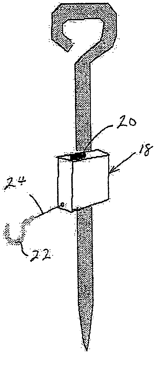
[0011] In the preferred embodiment of the present invention two grading pins are utilized. The grading pins have at one end a handle and at the other end a point thereby allowing for easy insertion by a user such as a construction worker into the ground. The grading pins when inserted are spaced apart from each other. A line casing is slideably disposed along the axis of one of the grading pins thereby adjusting the effective height of the line casing. The line casing has contained therein a spring loaded retractable string with the string having a hook on one end whereby the string is effectively stretched between the two grading pins. Thereafter the string is used as a reference line in order to determine the desired grade height

Problems solved by technology

A significant disadvantage of this is the difficulty of adjusting the height of the pivoting stick since the height of the pivoting portion may not be vertically adjusted.
Therefore, overall height adjustment may only by done by placing the entire pivoting stick at various depths in the adjacent soil which may be particularly difficult in dense soil or gravel.
Disadvantages of this device include the relative complexity and cost of construction as well as the difficulty in adjusting the vertical height.
Disadvantages of this device include its relative complexity and difficulty in adjusting the vertical height in various soil conditions.
As such it cannot be used during all phases of construction or where no curb is used such as in walkways and driveways.
U.S. Pat. No. 4,662,078 to Gammon et. al. entitled “CONSTRUCTION STRING REEL” and U.S. Pat. No. 5,704,131 to Courtney entitled “ADJUSTABLE PLUMB BOB AND LINE CAPABLE OF AUTOMATIC BRAKING AND RETRACTION” are principally directed to string retraction devices but fail to show how they should cooperate appropriately with grading pins.

Method used


Image

  • Tool for efficient setting of grading height
  • Tool for efficient setting of grading height
  • Tool for efficient setting of grading height

Examples


Embodiment Construction

[0015] Referring to FIGS. 1A, 1B&1C the preferred embodiment of the present invention is shown. Specifically, there is show grade pin 10 having a push handle 12 at one end, a shaft 14 and a pointed end 16 opposite the push handle 12. Grade pin 10 may be of whatever length is appropriate and may typically vary in length from 12″ to 30″, although it may be shorter or longer as desired. The grade pin 10 is preferably made of metal such as steel although it could me made of plastic or wood so long as it is of sufficient rigidity and durability.

[0016] Slideably disposed on the grade pin 10 is line casing 18. Line casing 18, in the preferred embodiment of the present invention has disposed therein a retractable string 24 which is spring loaded via a rotatable spring loading mechanism (not shown) so as to automatically retract when released. Disposed at the exposed end of string 24 is hook 22. Lever lock 20 is disposed on the outer cover of line casing 18 and when in a first position will...


PUM


Abstract

This invention relates generally to a tool for setting grading heights and more particularly to a tool for rapid and efficient measurement of grading heights between adjacent or opposing edges. Briefly stated, the preferred embodiment of the present invention consists of two grading pins spaced apart from each other and inserted into the surface adjacent where grading measurements are desired. Slidably disposed on one of the grading pins is a line casing having a spring loaded retractable string therein with the string having a hook on one end whereby the string is effectively stretched between the two grading pins. Thereafter the string is used as a reference line in order to determine the desired grade height.

Description

BACKGROUND OF THE INVENTION [0001] This invention relates generally to a tool for setting grading heights and more particularly to a tool for rapid and efficient measurement of grading heights between adjacent or opposing edges. [0002] Engineering and construction crews frequently have to set grading heights and thickness for various surfaces such as roadways, driveways, walkways and the like. Moreover, these heights or thicknesses must be determined a number of times during the course of their construction, specifically as each layer of sub base and base material (e.g. gravel) are deposited and perhaps compacted, and once again as the finish material is placed. Such finish materials may include asphalt, macadam, concrete, paving bricks or even fine or small size stones. [0003] Additionally, although the surfaces may be intentionally laid so as to be level and flat, it is frequently desirous to provide or to intentionally construct a surface which is not level. Such times are genera...

Claims


Application Information

Patent Timeline
IPC IPC(8): G01D21/00
CPCG01C15/02
Inventor WALLACH, GARRETTCHASE, ANTHONY
Owner WALLACH GARRETT
Learn More