
Optical branch device and optical coupler module

a branch device and optical coupler technology, applied in the field of optical branch devices, can solve the problems of large insertion loss, unfavorable generation of long 4-branched waveguide devices, and inability to produce devices of uniform quality with a high yield, and achieve the effect of high productivity and uniform quality

Inactive Publication Date: 2006-03-30
SANYO ELECTRIC CO LTD
View PDF5 Cites 6 Cited by
  • Summary
  • Abstract
  • Description
  • Claims
  • Application Information

AI Technical Summary

Benefits of technology

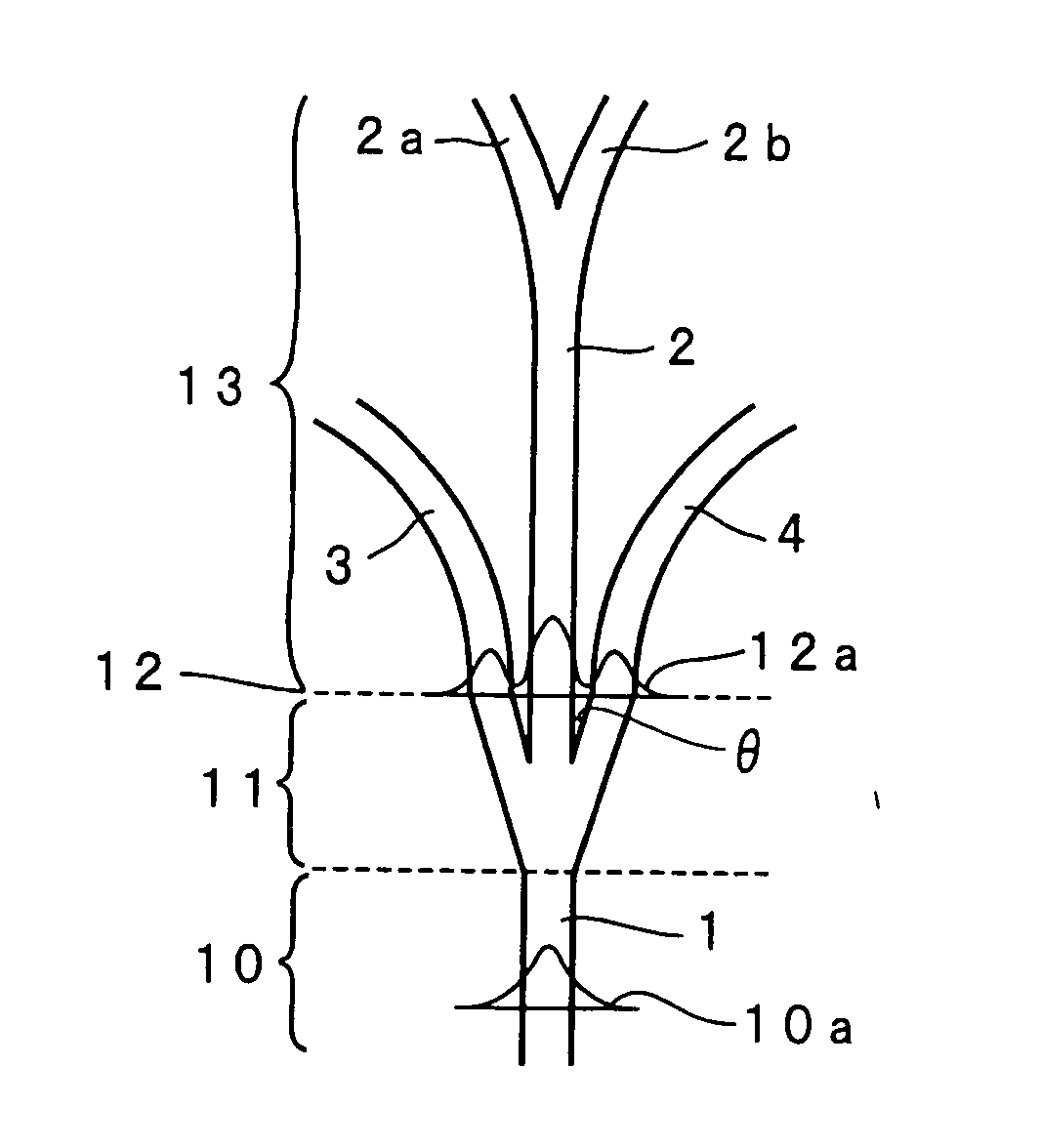
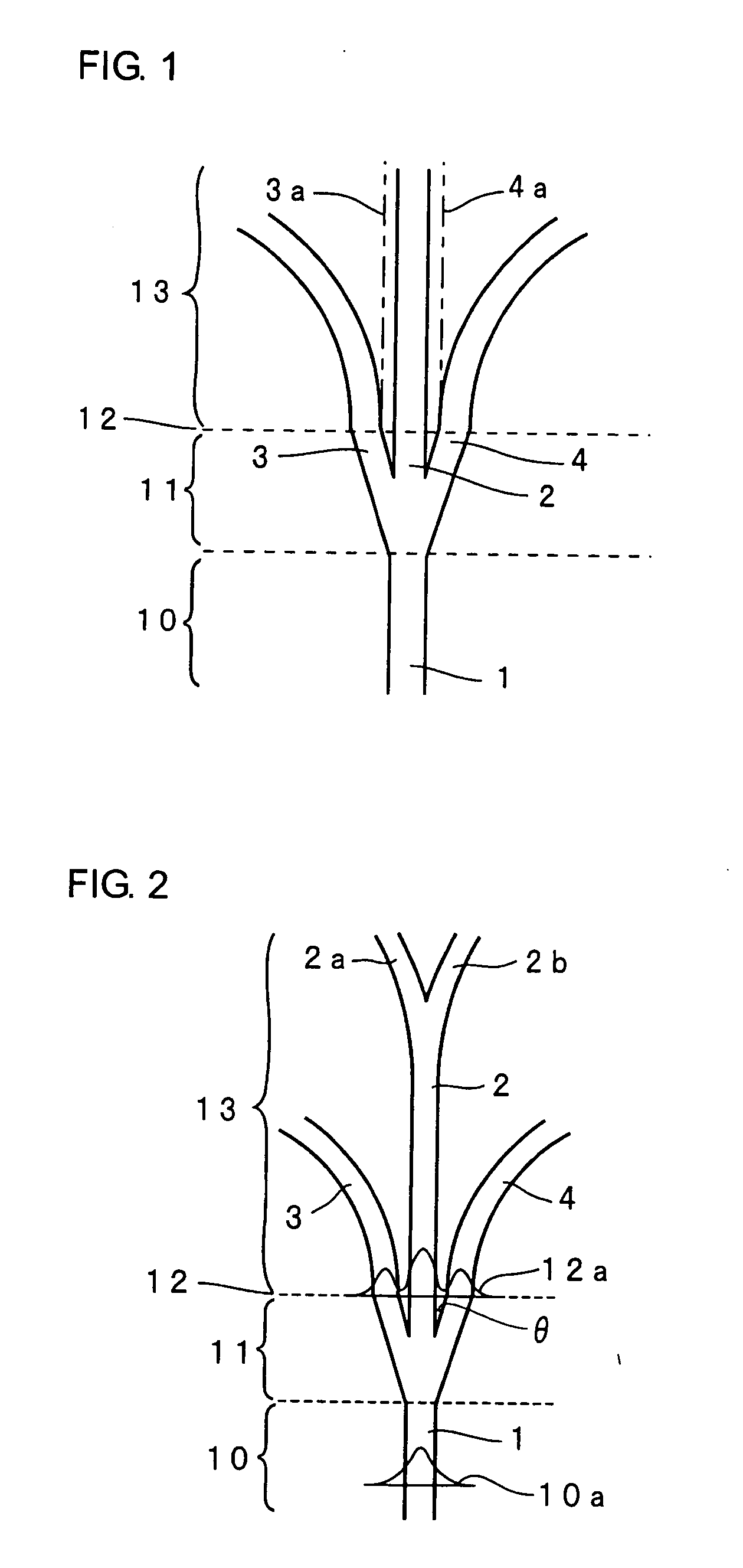
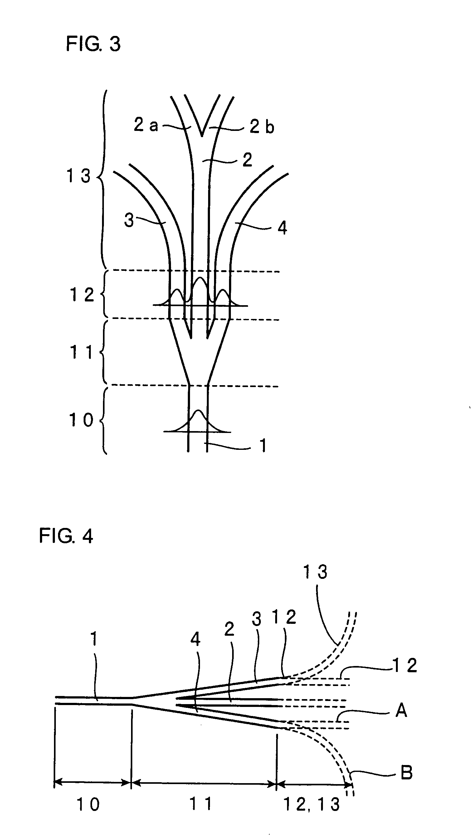
[0012] In the present invention, the parallel portion, wherein the second and third branch waveguides are positioned in parallel to the first branch waveguide, is formed between the branch portion and the divergent portion. The formation of this parallel portion causes stabilization of the optical intensity of the central first branch waveguide and the optical intensities of the second and third branch waveguides on both sides thereof. In the present invention, preferably, the first, second and third branch waveguides are each composed of a core having a relatively high refractive index and a clad arranged around the core and having a relatively low refractive index, and the interval pitch P (μm), in the transverse direction, between the first, second and third branch waveguides in the parallel portion and the refractive index difference (Δn) between the core and the clad are set in such a manner that C satisfies a relationship of C=0.5±0.2 wherein C is calculated by substituting P and Δn for an equation of C=Δn×P2. In the parallel portion, the interval pitch P (μm), in the transverse direction, between the first, second and third branch waveguides in the parallel portion and the refractive index difference (Δn) between the core and the clad are set in such a manner that C satisfies the relationship of C=0.5±0.2 wherein C is calculated by substituting P and Δn for the equation of C=Δn×P2, thereby to provide more excellent stabilization of the optical intensity of the central first branch waveguide and the optical intensities of the second and third branch waveguides on both sides thereof. In other words, even if the width of the optical waveguides or the refractive index difference Δn between the core and the clad is varied, an optical branch device can be produced in the state that effect of the variation is decreased.
[0037] The optical branch device of the present invention is less affected by variation in production conditions or the like. Accordingly, optical branch devices having a uniform quality can be produced with a high productivity.

Problems solved by technology

Thus, there is a problem that devices having a uniform quality cannot be produced with a high yield.
Thus, a very long 4-branched waveguide device is unfavorably formed.
If the length of waveguides becomes long in this manner, a large insertion loss (−10 log (the ratio of the output / the input) (unit: dB)) is unfavorably generated.

Method used


Image

  • Optical branch device and optical coupler module
  • Optical branch device and optical coupler module
  • Optical branch device and optical coupler module

Examples


Embodiment Construction

[0065] The present invention will be described by way of examples thereof hereinafter. However, the invention is not limited to the following examples, and can be carried out with any appropriate modification as long as the subject matter of the invention is not changed.

[0066]FIG. 1 is a plan view illustrating a waveguide of an optical branch device of an example according to the present invention. The waveguide of the optical branch device of the present example is composed of a basic portion 10, a branch portion 11, a parallel portion 12, and a divergent portion 13. In the branch portion 11, three branch waveguides, that is, a first branch waveguide 2, a second branch waveguide 3 and a third branch waveguide 4 are branched from a waveguide 1 in the basic portion 10. The first branch waveguide 2 is linearly extended continuously from the waveguide 1. The second branch waveguide 3 and the third branch waveguide 4 are formed in such a manner that the first branch waveguide 2 is inte...


PUM


Abstract

An optical branch device, comprising: a branch portion having a first branch waveguide extended linearly and continuously from a waveguide in a basis portion, and second and third branch waveguides extended in the directions farther from the first branch waveguide in such a manner that the first branch waveguide is interposed between the second and third branch waveguides; a parallel portion in which the second and third branch waveguides are positioned in parallel to the first branch waveguide; and a divergent portion in which the second and third branch waveguides are extended gradually farther from the first branch waveguide; wherein the interval pitch P (μm), in the transverse direction, between the first, second and third branch waveguides in the parallel portion and the refractive index difference (Δn) between the core and the clad are set in such a manner that C satisfies a relationship of C=0.5±0.2 wherein C is calculated by substituting P and Δn for an equation of C=Δn×P2.

Description

BACKGROUND OF THE INVENTION [0001] 1. Field of the invention [0002] The present invention relates to an optical branch device for branching signal light in optical communication or the like. [0003] 2. Description of the Related Art [0004] In optical communication or like, an optical branch device for branching input signal light into plural components is used as the need arises. [0005]FIG. 23 is a plan view of waveguides of a conventional 4-branched device. In this conventional 4-branched device, a basic waveguide 1 is branched into 4 waveguides 2a, 2b, 3 and 4 at a time. FIG. 24 is a graph showing dimensions of the waveguides when optical outputs of the branched waveguides are simulated about the conventional 4-branched device illustrated in FIG. 23. The transverse axis therein represents the length X in the transverse direction, and the vertical axis represents the length Z in the vertical direction. [0006]FIG. 25 is a graph showing results of the simulation. The transverse axis t...

Claims


Application Information

Patent Timeline
IPC IPC(8): G02B6/26
CPCG02B6/1221G02B6/138G02B6/125
Inventor HAYASHI, NOBUHIKOMATSUMOTO, MITSUAKIKURAMOTO, KEIICHIHIRANO, HITOSHI
Owner SANYO ELECTRIC CO LTD
Learn More