
Well use of space for low resistance coil design for write head

a write head and low resistance technology, applied in the field of magnetic recording heads, can solve the problems of coil height, write head expansion and protrusion, scratching of discs, etc., and achieve the effect of reducing coil resistance and avoiding shorting

Inactive Publication Date: 2006-03-30
HITACHI GLOBAL STORAGE TECH NETHERLANDS BV
View PDF6 Cites 3 Cited by
  • Summary
  • Abstract
  • Description
  • Claims
  • Application Information

AI Technical Summary

Benefits of technology

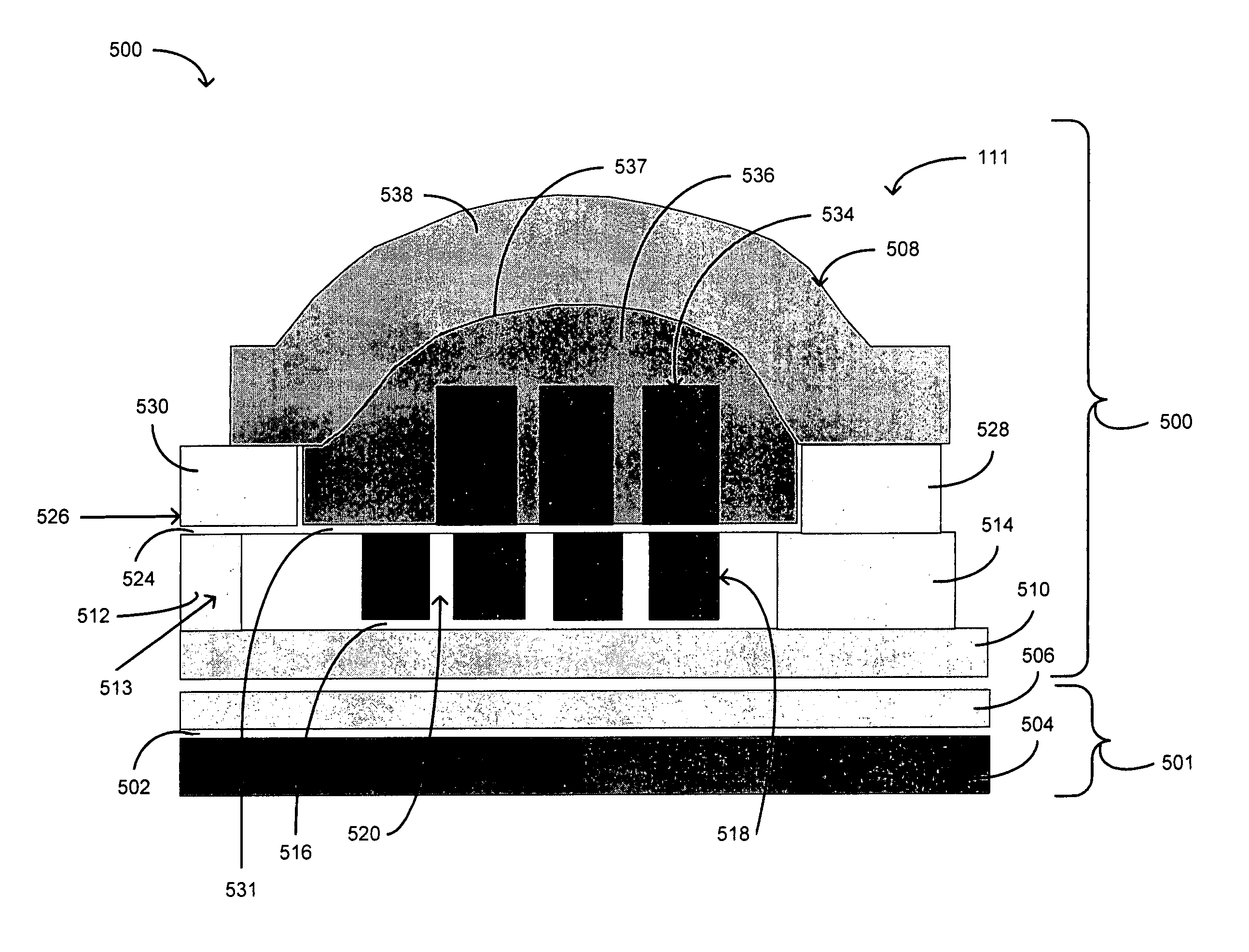
The present invention provides a structure and method for manufacturing a write head for a magnetic disk drive. The structure includes a P2 pole tip, a back gap layer, and a first insulation layer applied on top of the P2 pole tip and the back gap layer. Coil is developed on top of the first insulation layer and extends below the top of the P2 pole tip, and a second insulation layer pancakes the coil to insulate it. A P3 magnetic layer is formed on top of the second insulation layer, reducing coil resistance while avoiding shorting with the P3 magnetic layer. The invention also includes a magnetic read element sandwiched between first and second magnetic shields, and a disc drive embodying the invention. The technical effects include reducing coil resistance, avoiding shorting with the P3 magnetic layer, and improving the performance of the magnetic read element.

Problems solved by technology

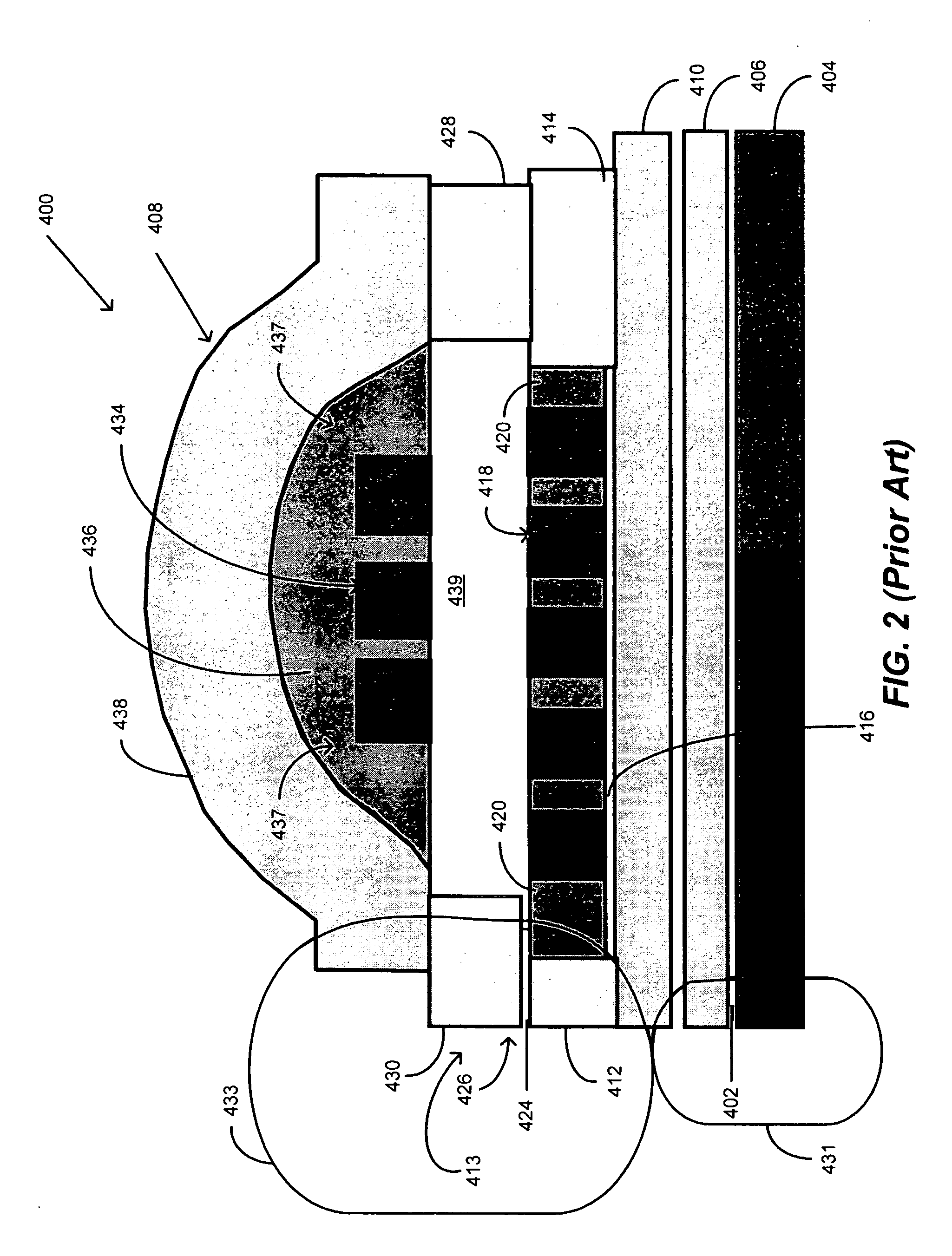
The problem with prior art write heads is that since it is desirable to keep the yoke length short, the coil (coils 418 and 434) needs to be narrow in an effort to attain an appropriate number of turns of the coil.
Therefore, the write head can become hotter during write operations thereby causing expansion and protrusion of the write head.
This protrusion is likely to cause the write poles to protrude too close to the disc, potentially causing scratching of the disc.
In some prior art techniques, problems associated with the height of the coil include but are not limited to the following.
Such shorting is clearly undesirable for many reasons, among which is a high potential for corrosion.

Method used


Image

  • Well use of space for low resistance coil design for write head
  • Well use of space for low resistance coil design for write head
  • Well use of space for low resistance coil design for write head

Examples


Embodiment Construction

[0030] The following description is the best embodiment presently contemplated for carrying out this invention. This description is made for the purpose of illustrating the general principles of this invention and is not meant to limit the inventive concepts claimed herein.

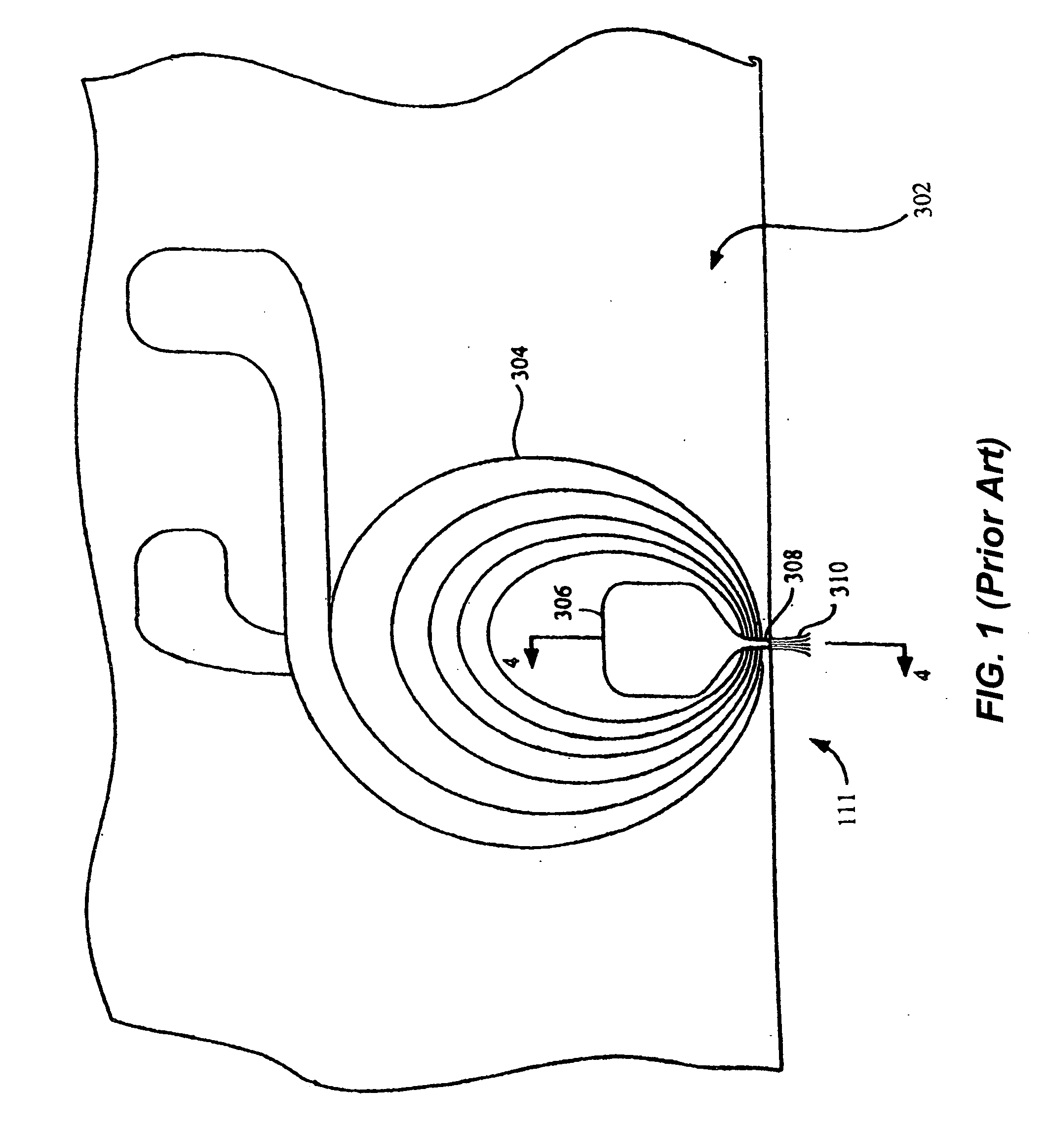
[0031] Referring now to FIG. 3, a top perspective view of a disc drive 100 embodying this invention is shown in accordance with an embodiment of the present invention. The disc drive 100 is shown to include a voice coil motor (VCM) 102, an actuator arm 104, a suspension 106, a flexure 108, a slider 111, a read-write head 112, a head mounting block 114, and magnetic disc or media 116. Suspension 106 is connected to the actuator arm 104 at the head mounting block 114. The actuator arm 104 is coupled to the VCM 102. The disc 116 includes a plurality of tracks 118 and rotates about axis 120. The tracks 118 are circular, each extending circularly around the surface of the disc 116 for storing magnetically-encoded data...


PUM

PropertyMeasurementUnit
thicknessaaaaaaaaaa
thicknessaaaaaaaaaa
temperaturesaaaaaaaaaa

Abstract

In one embodiment of the present invention, a write head includes a P2 pole tip, a back gap layer, and a first insulation layer applied on top and in between the P2 pole tip and the back gap layer. Coil, formed of copper, is developed on top of the first insulation layer and extends below the top of the P2 pole tip, a second insulation layer pancakes the coil to insulate it. A P3 magnetic layer is formed on top of the second insulation layer, the coil reducing coil resistance yet avoiding shorting with the P3 magnetic layer.

Description

CROSS REFERENCE TO RELATED APPLICATIONS [0001] This application is a continuation-in-part of prior U.S. patent application Ser. No. 10 / 652,878, filed on Aug. 29, 2003, entitled “METHOD FOR PATTERNING A SELF-ALIGNED COIL USING A DAMASCENE PROCESS”, the contents of which is incorporated herein by reference as though set forth in full and related to U.S. patent application Ser. No. 11 / 243,731, filed on Oct. 4, 2005 and entitled “SELF-ALIGNED COIL PROCESS IN MAGNETIC RECORDING HEADS”, the contents of which is incorporated herein by reference, as though set forth in full.BACKGROUND OF THE INVENTION [0002] 1. Field of the Invention [0003] This invention relates generally to the field of magnetic recording heads having coils inducing magnetic flux for writing on a magnetic medium (such as a magnetic disc) and more particularly, to recording heads having coil sizes taller in height causing lower coil resistance and thereby minimal write-induced protrusion. [0004] 2. Description of the Prior...

Claims


Application Information

Patent Timeline
Patent Type & Authority Applications(United States)
IPC IPC(8): B44C1/22C03C15/00G11B5/127G11B5/33A62C2/00A62D1/00G11B5/17G11B5/31G11B5/39H01F41/04
CPCG11B5/17G11B5/3116G11B5/313H01F41/041G11B5/3163G11B5/3967G11B5/3136
Inventor LEE, EDWARD HIN PONGNIKITIN, VLADIMIR
Owner HITACHI GLOBAL STORAGE TECH NETHERLANDS BV
Learn More