
Armor system

a technology of armor system and armor plate, applied in the field of armor system, can solve the problems of increasing the time and cost of armor application, inconvenient application, and the possibility of quick and easy armor application, and achieve the effect of quick and easy application and high protection

Inactive Publication Date: 2006-03-30
ARMOR SYST INT
View PDF4 Cites 137 Cited by
  • Summary
  • Abstract
  • Description
  • Claims
  • Application Information

AI Technical Summary

Benefits of technology

[0016] The foregoing problems are overcome and other advantages are provided by an armor system that can be quickly and easily applied to a body to be protected and that provides a high degree of protection from a projectile.
[0018] The present invention provides an armor system that can be quickly and easily applied to a body or object to be protected. The armor system preferably includes one or more armor units that include a pressure sensitive adhesive such as, for example, a “peel and stick” adhesive to adhere the armor system to the body to be protected. The pressure sensitive adhesive adheres to most surfaces and adheres extremely well to high-energy surfaces such metal, wood, concrete, glass, or other smooth surfaces. The pressure sensitive adhesive can be formed on either the backside of the armor system for application to an outer surface of the body or structure or can be formed on the front side of the armor system for application to an inner surface of the body or structure. Alternatively, the pressure sensitive adhesive can be formed on both the front and back side of the armor system for an even wider range of applications.
[0022] In another possible embodiment, the armor unit includes a self-healing layer in which the void left by the projectile is filled and the armor unit is sealed to prevent the protective materials from spilling out of the outer case. In one arrangement of the self-healing embodiment, the armor unit includes plural bags of loose ceramic fill combined with a tensioned steel spring and a layer of foam packets each of which include foam that expands and hardens when exposed to air. When the armor unit is pierced by a projectile the foam expands into the void left by the projectile and hardens preventing the loose ceramic fill from spilling out of the outer case. In another embodiment, the armor unit includes a layer of tubes filled with ceramic material located adjacent a layer of foam packets. Each tube includes springs located at each end to place the ceramic material under compression and explosive end caps at each end. When the tube is shattered by a projectile the ceramic material is forced by the springs into the void created by the projectile. Since the foam packets is the first layer to encounter the projectile at least one of the foam packets is ruptured by the projectile so that the foam is exposed to air and expands hardens to prevent the ceramic material from spilling out of the outer case.
[0024] The present invention further provides a lighter weight ceramic layer that includes perforated ceramic tiles. Each ceramic tile includes plural holes that reduce the weight of the ceramic tile but allows the ceramic tile to retain its strength properties. In one embodiment, the holes are filled with a polymer material capable of bonding a high strength protective material, such as, for example, a metal plate to the ceramic tile.
[0025] The present invention provides an armor system that is lightweight and that can be quickly and easily applied to many bodies and vehicles. The armor system is preferably flexible so that it can be easily applied to either flat or non-flat areas on military or law enforcement personnel, vehicles, critical systems such as, for example, oil and gas pipelines, and other objects where protection from weapons or explosives are required. One example of such use is the application of the flexible armor system to surfaces of helicopter fuselages to protect pilots and critical flight systems.
[0026] The present invention provides a light flexible armor that easily conforms to different surfaces and shapes, that adheres aggressively to a variety of curved or flat surfaces, and that is capable of stopping numerous types of threats.

Problems solved by technology

Since the armor must be incorporated into these structures it is not possible to quickly and easily provide armor for protection for structures or bodies that do not have “built-in” armor.
However, this usually requires the application of a liquid glue to the armor and / or the body to which the armor is being attached.
This increases the time and cost of applying the armor.
Furthermore, such glues are costly, inconvenient to apply, and may be hazardous due to fumes or other hazardous chemicals involved.
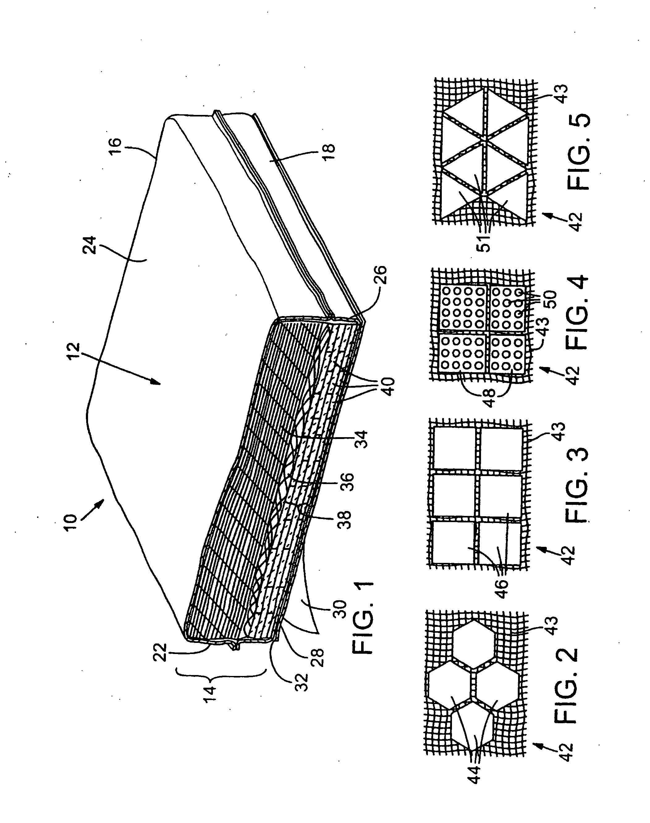
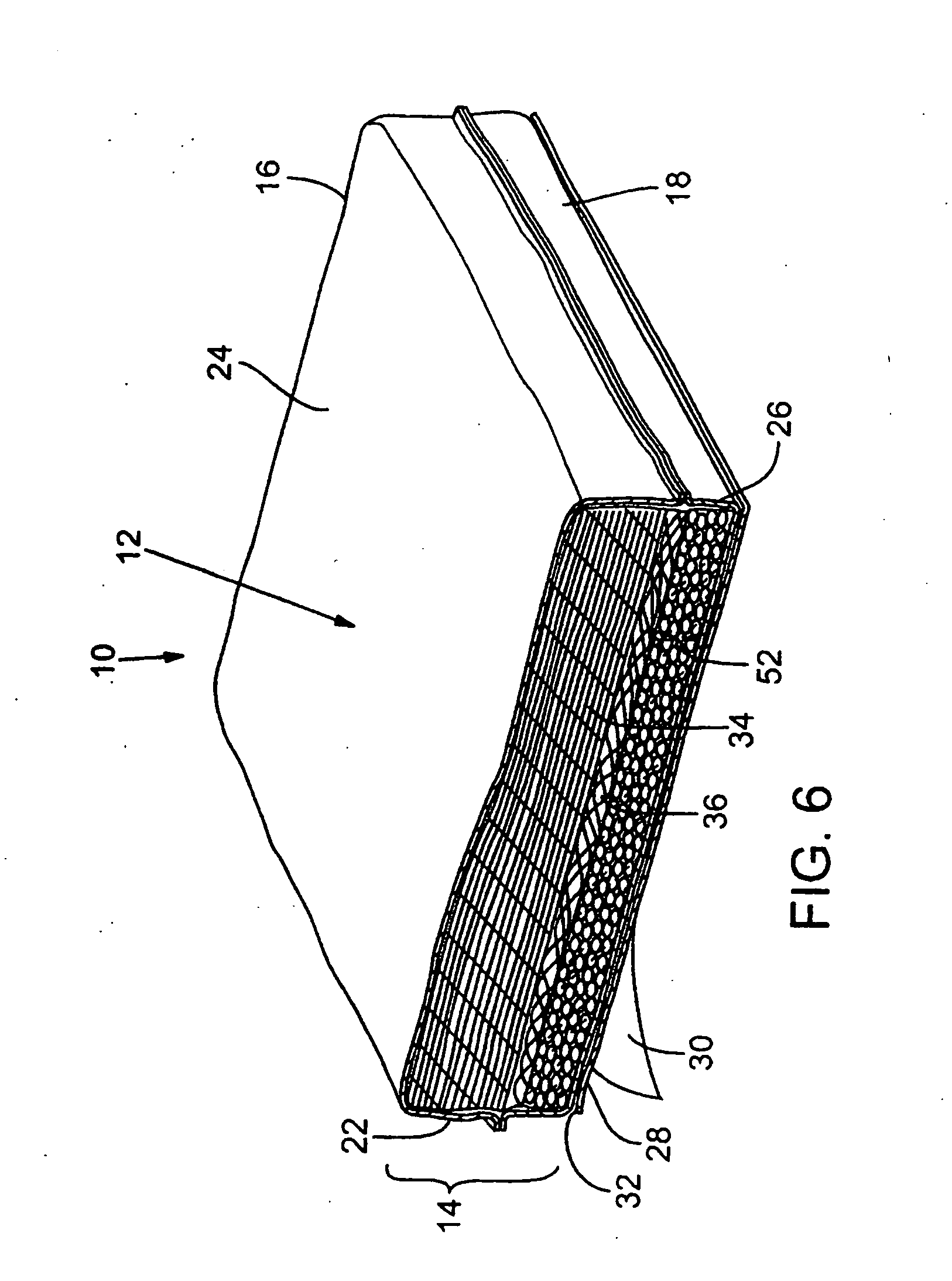
Also, such liquid glues require storage, which further increases costs especially if a special storage facility is required.
However, magnetic armor systems are limited in use to metallic bodies and structures and are not suitable for some applications.
Another problem encountered with prior art armor systems is weight.
However, the weight of the steel plates makes such armor systems undesirable.
Furthermore, with the development of armor piercing projectiles the thickness of the steel plates used in armor systems has increased which further increases the cost and weight of the armor system and decreases its ability to conform to some surfaces.
However, upon impact the ceramic tiles shatter creating voids and dangerous fragments.
This precise spacing of the ceramic tiles is time consuming and adds to the cost of manufacture of the armor system.
Furthermore, if the spacing is not right the armor system may not be effective.
However, as with the ceramic sheets, the ceramic tiles may shatter creating dangerous fragments.
Additionally, the cost of the ceramic tiles is expensive.
Another problem encountered with prior armor systems is their inability to conform to some surfaces.
Another problem with prior armor systems is that any projectiles that penetrate the armor system create voids in the armor system leaving the body to be protected vulnerable to damage from additional projectiles.
For example, in marine environments a void created by a projectile may allow water to penetrate and damage the body to be protected.
However, none of the prior art discloses an armor system that can be quickly and easily applied to a body or structure.

Method used


Image

  • Armor system
  • Armor system
  • Armor system

Examples


Embodiment Construction

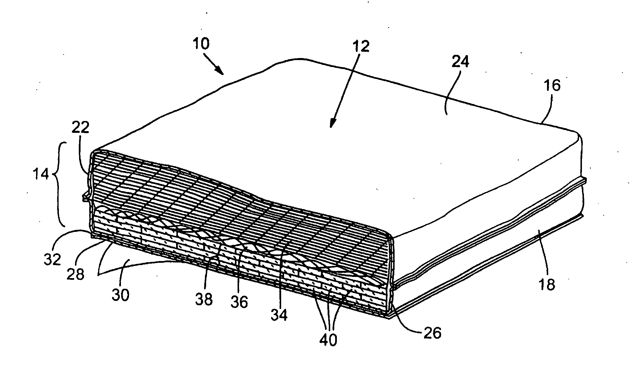
[0053] In certain embodiments, the armor system of the present invention provides an armor that can be quickly and easily applied to a body to be protected and adapted to a variety of situations depending on the level of threat and the level of protection needed. The armor system may include plural armor units that include an outer case that can be filled with a variety of protective materials either alone or in combination with other protective materials. The type and combination of materials that are enclosed within the outer case depend on several factors such as, for example, the level of threat and protection that is needed against the threat, the weight of the armor system, the need for the armor system to conform to the body to which it is to protects, and the cost of the armor system.

[0054]FIG. 1 shows an armor unit 10, one or more of which make up the armor system of the present invention. Although only one armor unit 10 is shown it is understood that many more armor units...


PUM

PropertyMeasurementUnit
Forceaaaaaaaaaa
Pressureaaaaaaaaaa
Strengthaaaaaaaaaa

Abstract

An armor system is provided having an outer case of woven or unidirectional fibers filled with one or more protective materials. The outer case includes a pressure sensitive adhesive bonded to one side for quick and easy application to a body to be protected. The protective materials may include ceramic material which may be in the form of ceramic tile sheets, loose ceramic balls, or perforated tiles, multiple layers of woven or unidirectional cloth, and steel mesh. These materials may be used alone or in any combination. A tensioned energy layer and / or a self-healing layer may be provided to fill a void created by a projectile.

Description

[0001] This invention claims the benefit of co-pending U.S. Provisional Application No. 60 / 373,755, entitled “Armor System”, filed Apr. 17, 2002, the entire disclosure of which is hereby incorporated by reference as if set forth in its entirety for all purposes.TECHNICAL FIELD [0002] The present invention is directed to armor systems and more particularly to an armor system that can be quickly and easily applied to an animate or inanimate body to be protected. BACKGROUND OF THE INVENTION [0003] Many and various types of armor systems are known for shielding personnel, vehicles, and equipment from injury and / or damage from projectiles. Such armor systems are typically used in military environments to protect military personnel as well as military equipment such as, for example, aircraft, tanks, ships, and other vehicles. Armor systems are also used in law enforcement and other environments in which protection from armor piercing projectiles or other type of ballistic missiles is desi...

Claims


Application Information

Patent Timeline
IPC IPC(8): F41H5/02F41H5/04
CPCF41H5/0492F41H5/0428
Inventor HENRY, JAMES J M
Owner ARMOR SYST INT
Learn More