
Apparatus for cutting a workpiece

a workpiece and apparatus technology, applied in the field of apparatus for forging workpieces, can solve the problems of impairment of forging process and forging quality, and the likelihood of excessive torsional strain on the workpiece, and achieve the effect of high upsetting force and favorable forging quality

Active Publication Date: 2006-03-30
GFM BETEILIGUNGS & MANAGEMENT
View PDF3 Cites 9 Cited by
  • Summary
  • Abstract
  • Description
  • Claims
  • Application Information

AI Technical Summary

Benefits of technology

[0003] The invention is thus based on the object of providing an apparatus for forging a workpiece of the kind mentioned above in such a way that a favorable forging quality can be ensured even at high numbers of impact of the forging tools and high upsetting forces between the clamping head and counter-holder.
[0005] Since as a result of this measure the rotational entrainment of the counter-holder by the workpiece can be omitted, which workpiece is driven synchronously in an intermittent manner from both ends, the rotational advancement of the workpiece can be adjusted in an advantageous manner to the drive of the forging tool, thus ensuring that a predetermined forging sequence can be maintained. An additional factor is that these drive units can be provided with a smaller configuration due to the division of the torque to two drive units, which torque is necessary for the rotational advance of the workpiece. The additional drive of the counter-holder also reduces the torsional strain on the workpiece.

Problems solved by technology

Despite these measures, there is the likelihood of an excessive torsional strain on the workpiece, especially in the case of an increasing number of impacts of the forging tools and higher requirements placed on the upsetting force to be applied between the clamping head and counter-holder on the workpiece, because in these cases one must expect respectively high frictional forces in the axial bearings of the counter-holder and high inertia forces by the intermittent rotary movement of the workpiece.
Relative rotations are consequently obtained between the counter-holder and the clamping head which need to be compensated through the workpiece, leading to impairments in the forging process and the forging quality.

Method used


Image

  • Apparatus for cutting a workpiece
  • Apparatus for cutting a workpiece
  • Apparatus for cutting a workpiece

Examples


Embodiment Construction

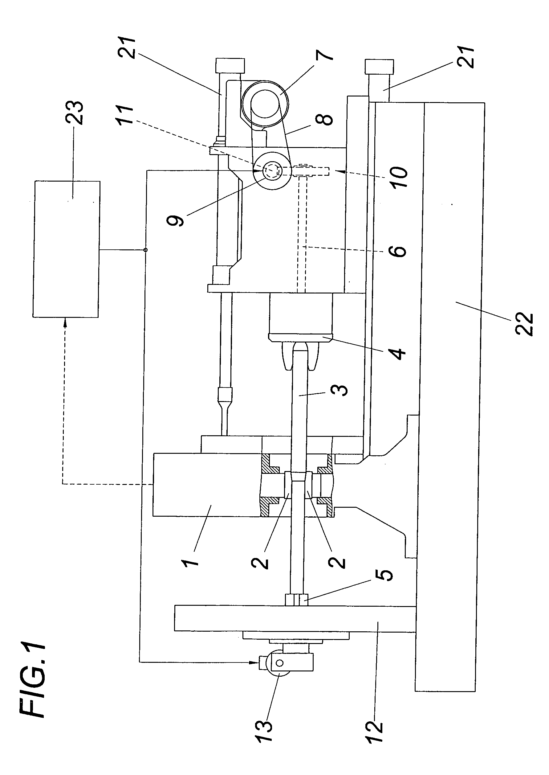
[0011] According to FIG. 1, the illustrated apparatus comprises a forging unit 1 with mutually opposite paired forging tools 2 for a workpiece 3 which is clamped on the one hand in the clamping head 4 and is supported on the other hand on a counter-holder 5. The clamping head 4 is driven in a conventional manner via a spindle 6, namely with the help of a continuous rotational drive 7 which drives a drive shaft 9 for a worm gear 10 via a belt dive 8, with the worm 11 being held in an axially displaceable way relative to the drive shaft 9 and resting on a spring brake in order to ensure an intermittent drive of the spindle 6 depending on the respective engagement of the cutting tools 2.

[0012] The counter-holder 5 is rotatably held in a conventional manner in a frame 12 via radial and axial bearings. In contrast to conventional constructions, an intermittent rotational drive 13 is provided for the counter-holder 5 which corresponds substantially with the intermittent rotational drive ...


PUM

PropertyMeasurementUnit
axial displacementaaaaaaaaaa
resonance behavioraaaaaaaaaa
frictional forcesaaaaaaaaaa

Abstract

An apparatus is described for forging a workpiece (3) with an intermittently drivable clamping head (4) for the workpiece (3) and with a counter-holder (5) for receiving the end of the workpiece (3) averted from the clamping head (4), which counter-holder is rotatably held in a frame (12). In order to provide advantageous constructional conditions it is proposed that the counter-holder (5) is connected with an intermittent rotational drive (13) which can be triggered synchronously to the clamping head (4).

Description

FIELD OF THE INVENTION [0001] The invention relates to an apparatus for forging a workpiece with an intermittently drivable clamping head for the workpiece and with a counter-holder for receiving the end of the workpiece averted from the clamping head, which counter-holder is rotatably held in a frame. DESCRIPTION OF THE PRIOR ART [0002] In order to support a workpiece during forging not only by way of a clamping head drivable through a spindle, but also to provide support at the end opposite of the clamping head, a counter-holder is used which is rotatably held in a frame coaxially to the spindle of the clamping head. The counter-holder, which may optionally be used to exert an upsetting force on the workpiece, is co-rotated by the workpiece which is fixed against rotation during the application of the forging tool. This requires an intermittent drive of the clamping head in order to avoid impermissible torsional strain on the workpiece. For this purpose it is known (AT 278 481 B) ...

Claims


Application Information

Patent Timeline
Patent Type & Authority Applications(United States)
IPC IPC(8): B21J13/10B21J13/12
CPCB21J13/12
Inventor KOPPENSTEINER, ROBERT
Owner GFM BETEILIGUNGS & MANAGEMENT
Learn More