
Image reading apparatus

Inactive Publication Date: 2006-03-23
FUJIFILM HLDG CORP +1
View PDF8 Cites 2 Cited by
  • Summary
  • Abstract
  • Description
  • Claims
  • Application Information

AI Technical Summary

Benefits of technology

[0007] A primary object of the present invention is to provide an image reading apparatus that can automatically distinguish between front and rear surfaces of an original.
[0008] Another object of the present invention is to provide an image reading apparatus that prevents image reading from the original being loaded in reverse.
[0012] Moreover, it is preferable that the focusing regions include at least three regions that are a center region of the image reading area and a pair of edge regions that are symmetric with respect to the center region and being located at opposite corners of the image reading area. The arrangement of the edge regions especially allows to keep long distance between two focusing regions.
[0013] According to the present invention, the image reading apparatus detects the partial focusing positions, which are positions of the image-forming lens at which the focusing regions are respectively focused. The image reading apparatus then automatically judges whether the original is loaded in the film carrier properly or not by inspecting the curl of the original based on the partial focusing positions. Therefore, the image reading apparatus of the present invention improves operational efficiency in loading the original in the film carrier. In addition, the image reading apparatus of the present invention prevents the image reading from the original being loaded in reverse by giving warning when the original is not loaded properly.

Problems solved by technology

However, it is time consuming to distinguish the front surface from the rear surface by the visual check.
Further, it is difficult to distinguish between the front and rear surfaces of the transparent originals like the photographic film.
Therefore, there is a possibility of not noticing that the image has been reversed in the printing even after looking at printed photographs.

Method used


Image

  • Image reading apparatus
  • Image reading apparatus
  • Image reading apparatus

Examples


Embodiment Construction

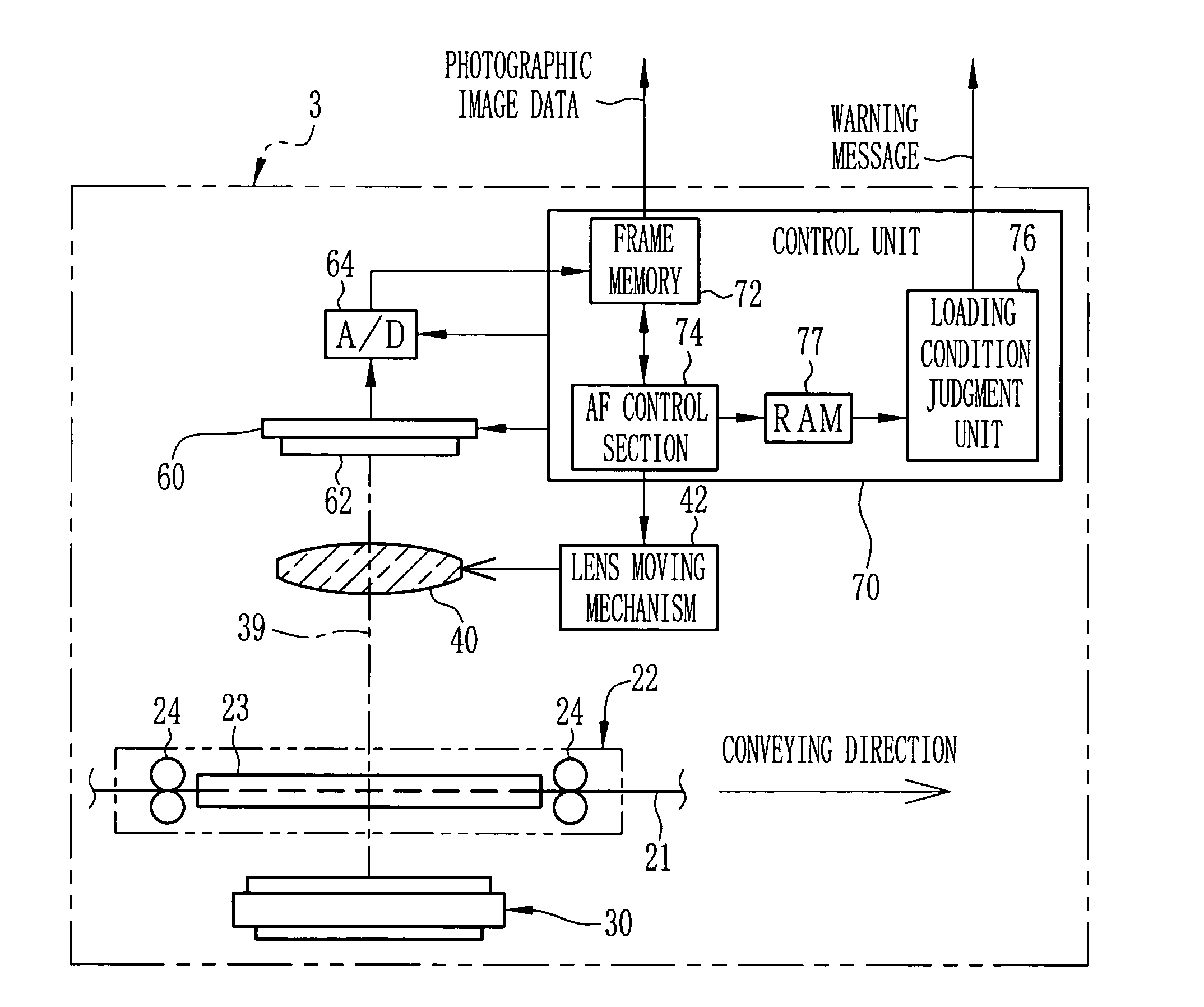
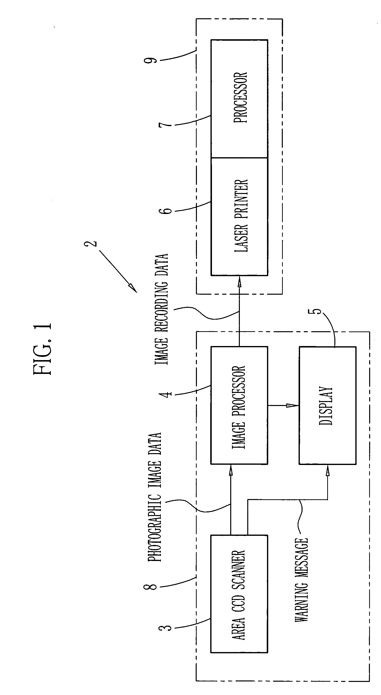
[0021] A digital print system 2 shown in FIG. 1 is constituted of an input apparatus 8 and an output apparatus 9. The input apparatus 8 includes an area CCD scanner 3, an image processor 4 and a display 5, and reads an image of each frame of a photographic film 21 (see FIG. 2), which is an original to be read. The output apparatus 9 includes a laser printer 6 and a processor 7, and prints the read image of the each frame of the photographic film 21 on a recording medium.

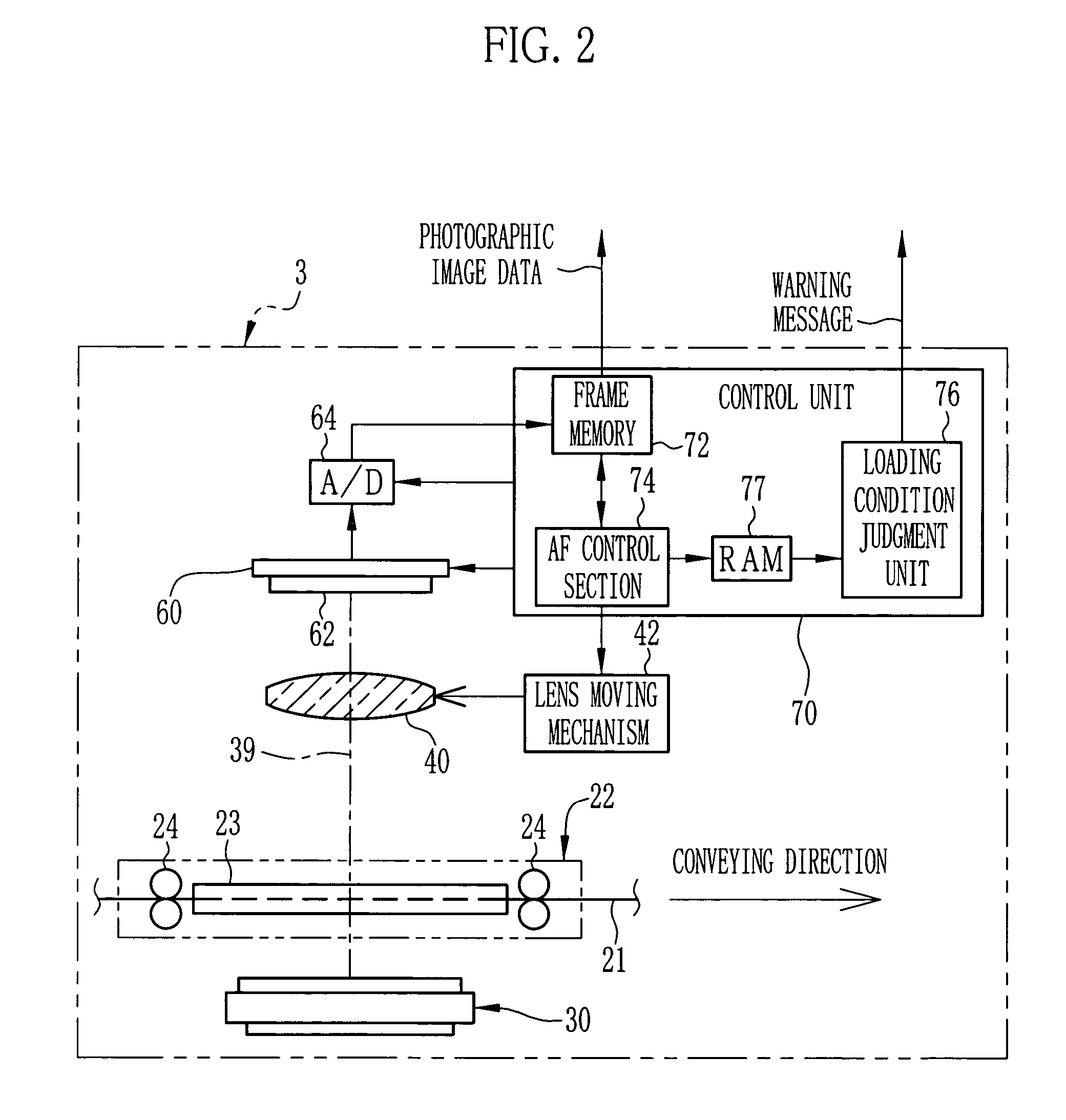
[0022] The area CCD scanner 3 reads the photographic image of the each frame of the photographic film 21 that resides in an image reading area 80 (see FIG. 3). Image signals of analog outputted from the area CCD scanner 3 are digitized by an analog-digital (A / D) converter 64 to be photographic image data, then the photographic image data is sent to the image processor 4. The image processor 4 performs various image processing procedures, including density correction, color correction, sharpness control and so forth,...


PUM


Abstract

An automatic focusing (AF) control section performs focus detection for each of focusing regions provided in an image reading area to detect positions of an image-forming lens where the focusing regions are focused as partial focusing positions. A loading condition judgment unit judges the loading condition of a photographic film by inspecting a curl of the image reading area based on each of the partial focusing positions. When the image reading area is bowed such that the center thereof is projected toward an area CCD, the photographic film is judged being loaded in reverse, and a warning message is displayed on a display. In this case, image reading of the photographic film is not executed.

Description

BACKGROUND OF THE INVENTION [0001] 1. Field of the Invention [0002] The present invention relates to an image reading apparatus for reading an image from an original being loaded in a film carrier. [0003] 2. Description Related to the Prior Art [0004] Image reading apparatuses that read an image recorded on an original, by forming an optical image on a photoreceptive surface of a photoelectric converter such as a charge coupled device (hereinafter referred to as the CCD) image sensor and the like, are known. A film scanner is one of the image reading apparatuses and reads photographic films as the originals (U.S. Pat. No. 6,816,287). One side of a base of the photographic film is coated with emulsion, and the emulsion-coated side is a front surface (reading side) of the photographic film on which the image is recorded. The photographic film is loaded in a film carrier of the film scanner such that the front surface faces to the photoreceptive surface of the CCD. A rear side of the p...

Claims


Application Information

Patent Timeline
IPC IPC(8): G03D13/04
CPCG03D13/04
Inventor SAKAGUCHI, YASUNOBU
Owner FUJIFILM HLDG CORP
Learn More