
Portable rechargeable night light

a rechargeable, night light technology, applied in the direction of light source combinations, coupled device connections, built-in power, etc., can solve the problems of not being able to provide a light emitting method with sensory decorations to meet the requirements of special occasions such as parties or romantic atmosphere, and not being able to allow consumers to make changes

Inactive Publication Date: 2006-03-23
YOUNG JEAN
View PDF3 Cites 49 Cited by
  • Summary
  • Abstract
  • Description
  • Claims
  • Application Information

AI Technical Summary

Benefits of technology

[0006] a light emitting component, being electrically coupled to said control circuit, and adopting the light emitting mode selected by the module switch, and producing a lighting effect on a decorative object by projecting the light from a light emitting position on the end surface of the base; and

Problems solved by technology

In other words, the prior-art night light can provide a monotonous light source and a limited illumination, but cannot provide a light emitting method with sensory decorations to meet the requirements for special occasions such as parties or romantic atmosphere.
The external chassis covered the exterior of the bulb is manufactured and shipped out from the factory as a fixed style, which does not allow consumers to make changes as they wish to meet their mood or interior decoration.
Then, one will keep many unused night lights in one's house, and thus causing a storage issue and wasting money.
However, unexpected power disconnection due to fire, earthquake or typhoon may occur, and the night light will lose its function completely.

Method used


Image

  • Portable rechargeable night light
  • Portable rechargeable night light
  • Portable rechargeable night light

Examples


Embodiment Construction

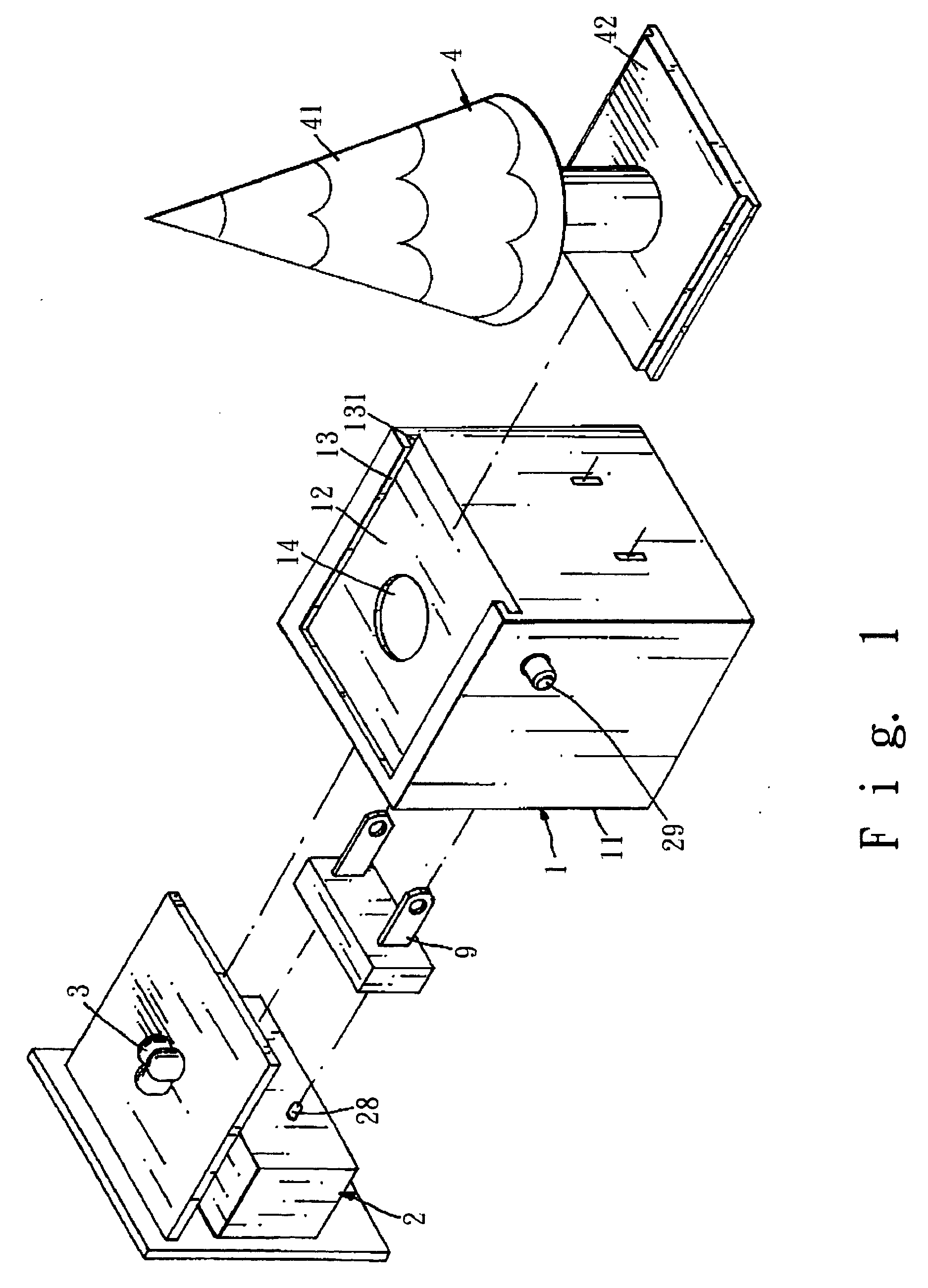
[0015] Please refer to FIGS. 1 to 5 for a preferred embodiment of the present invention. The night light according to the present invention comprises a base 1, a control circuit 2 and a light emitting device 3 both disposed on the base 1, and a replaceable luminous decorative object 4 as shown in FIG. 1. The light emitting method for the light emitting device 3 is selected and control by a module switch 23, and the operating power supply is input through a replaceable electrically coupled device 9 to fit different voltages.

[0016] The base 4 as shown in FIG. 1 comprises a built-in assembling space 11 for installing electric components such as the control circuit 2 and the light emitting component 3; and a light emitting space 12 containing an embedding module 13 and the surface of the light emitting space 12 has a light-transmittable means 14 (as shown in FIG. 1). Such device could be either an uncovered hole or a hole covered with a transparent sheet. In other embodiments, the surf...


PUM


Abstract

This invention discloses a portable rechargeable night light, which comprises a replaceable luminous decorative object, a night light with an electric accumulator for emergency lighting, a base including an embedding module; a control circuit including a transformer for providing an operating power supply and a charge power supply through an electrically connected device with different voltages and setting a plurality of operating modes by a programmable control unit, and users select the setting through the module switch; a light emitting component electrically connected to and controlled by said control circuit to emitting light from a light emitting device from an end surface of the base to a luminous decorative object; and a luminous decorative object embedded on the base, of which the light emitting mode can be changed to select different operations and sensing effects of the light.

Description

FIELD OF THE INVENTION [0001] The present invention relates to a night light, more particularly to a portable rechargeable night light. BACKGROUND OF THE INVENTION [0002] A traditional night light usually comprises a housing having a power socket connected to a corresponding wall socket for obtaining electric power supply, a lamp base disposed at the top surface of the housing and installing a 3W bulb as a light source and a decorative external chassis. Some manufacturers adopt a rotary external chassis as a decorative lampshade. A general switch or a light-sensor switch is used for the control of turning on and off the night light. The light source of the prior-art night light generally adopts a single bulb or other light that can produce only one fixed color light source. In other words, the prior-art night light can provide a monotonous light source and a limited illumination, but cannot provide a light emitting method with sensory decorations to meet the requirements for special...

Claims


Application Information

Patent Timeline
Patent Type & Authority Applications(United States)
IPC IPC(8): H01R33/00
CPCA47G33/06F21S8/035F21S9/02F21S10/005F21Y2113/005F21W2121/00F21Y2101/02F21Y2113/002F21V23/04F21Y2115/10F21Y2113/10F21Y2113/13
Inventor YOUNG, JEAN
Owner YOUNG JEAN
Learn More