
Organic electroluminescent display device having plurality of driving transistors and plurality of anodes or cathodes per pixel

Active Publication Date: 2006-03-23
SAMSUNG DISPLAY CO LTD
View PDF23 Cites 50 Cited by
  • Summary
  • Abstract
  • Description
  • Claims
  • Application Information

AI Technical Summary

Benefits of technology

[0024] An embodiment of the present invention provides an organic EL display device, which includes at least two driving transistors and an organic light emitting diode having at least two first electrodes and a common second electrode per pixel. Accordingly, even if a short circuit occurs between one of the first electrodes and the common second electrode, the organic light emitting diode still emits light using the other first electrode, thereby eliminating effects of the short circuit.

Problems solved by technology

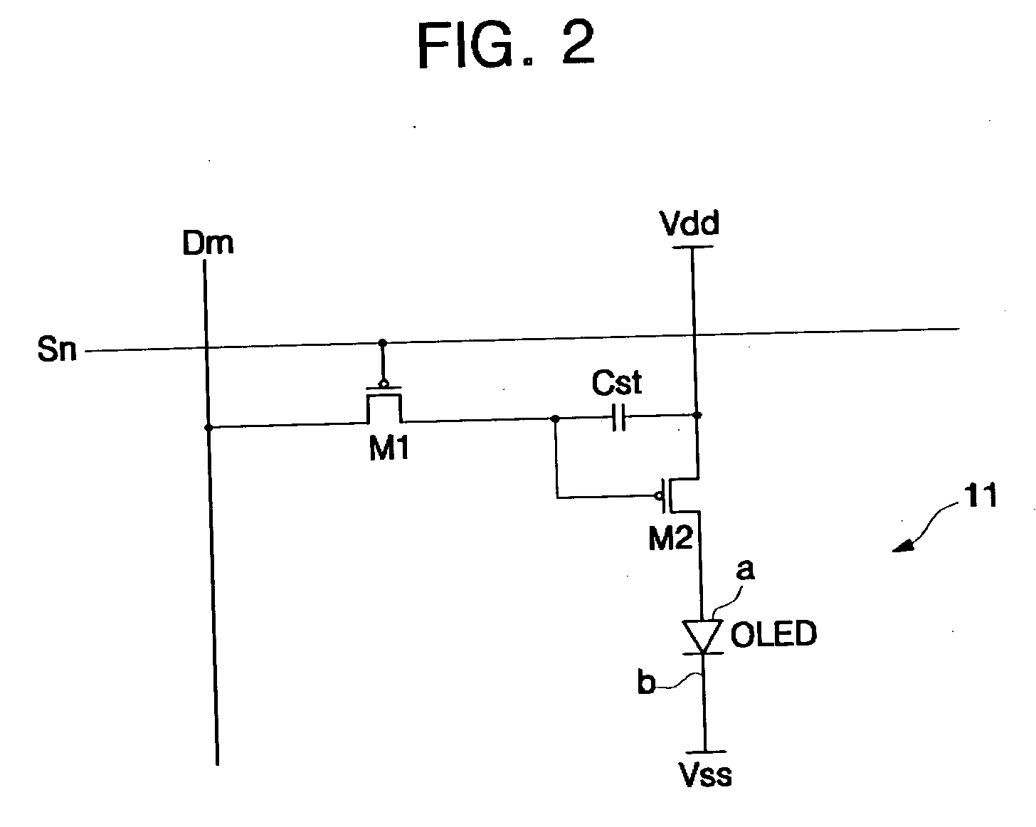
However, the conventional organic light emitting diode has one anode and a common cathode per unit pixel; and a relationship between the anode and the cathode may be affected by fine particles inserted between the anode and the cathode during a manufacturing process, a pattern failure of a lower layer, and / or an external pressure.

Method used


Image

  • Organic electroluminescent display device having plurality of driving transistors and plurality of anodes or cathodes per pixel
  • Organic electroluminescent display device having plurality of driving transistors and plurality of anodes or cathodes per pixel
  • Organic electroluminescent display device having plurality of driving transistors and plurality of anodes or cathodes per pixel

Examples


Embodiment Construction

[0038] The present invention will now be described with reference to the accompanying drawings, in which exemplary embodiments of the invention are shown.

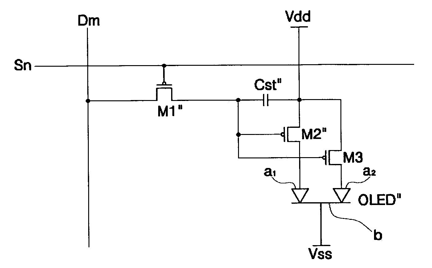
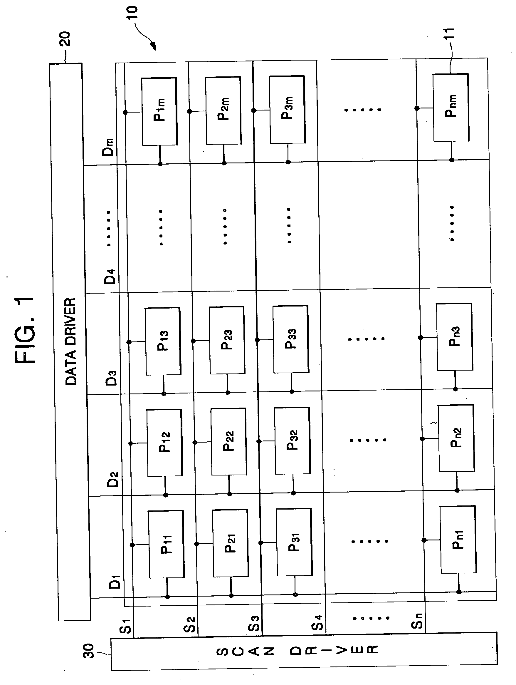
[0039]FIG. 5 is a circuit diagram of one pixel according to an embodiment of the present invention, i.e., one representative pixel among N×M pixels, which is connected to a data line Dm and a scan line Sn.

[0040] Referring to FIG. 5, the pixel circuit includes a switching transistor M1″, a first driving transistor M2″, a second driving transistor M3, a capacitor Cst″, and an organic light emitting diode OLED″ having first and second anodes a1 and a2. The first and second driving transistors M2″ and M3 are each comprised of a PMOS transistor.

[0041] The switching transistor M1″ has a gate connected to the scan line Sn and transmits a data voltage from the data line Dm connected to its source to gates of the first and second driving transistors M2″ and M3 in response to a selection signal from the scan line Sn.

[0042] The first driv...


PUM


Abstract

An organic electroluminescent (EL) display device having a plurality of pixel circuits formed at crossing points of a plurality of scan lines and a plurality of data lines is provided. Each pixel circuit includes at least two driving transistors connected to a first power voltage line, the at least two driving transistors receiving a data signal through at least one of the data lines and outputting a driving current corresponding to the data signal; and an organic light emitting diode having at least two first electrodes respectively connected to the at least two driving transistors and emitting a light corresponding to the driving current. The organic light emitting diode has the at least two first electrodes and a common second electrode per pixel in order to prevent the whole pixel from not operating due to a short circuit occurring between one of the first electrodes and the second electrode.

Description

CROSS-REFERENCE TO RELATED APPLICATION [0001] This application claims priority to and the benefit of Korean Patent Application No. 10-2004-0075655, filed Sep. 21, 2004, the entire content of which is incorporated herein by reference. BACKGROUND OF THE INVENTION [0002] 1. Field of the Invention [0003] The present invention relates to an organic electroluminescent (EL) display device, and more particularly, to an organic EL display device which includes at least two driving transistors and an organic light emitting diode having at least two first electrodes and a common second electrode per pixel in order to operate the pixel due to a short circuit occurring between one of the first electrode and the second electrode [0004] 2. Description of the Related Art [0005] An organic light emitting diode is an emissive device which emits fluorescent light by recombining electrons supplied from a cathode and holes supplied from an anode. An EL display device, which employs the organic light emi...

Claims


Application Information

Patent Timeline
IPC IPC(8): G09G3/30
CPCG09G3/3233H01L27/3276G09G2300/0842G09G2300/0443H10K59/131G09G3/30
Inventor KIM, EUN-AHLEE, JEONG-NO
Owner SAMSUNG DISPLAY CO LTD
Learn More