
Method for implementing continuous radio frequency (RF) alignment in advanced electronic warfare (EW) signal stimulation systems

Active Publication Date: 2009-09-24
AIRPORTS AUTHORITY OF INDIA
View PDF40 Cites 7 Cited by
  • Summary
  • Abstract
  • Description
  • Claims
  • Application Information

AI Technical Summary

Benefits of technology

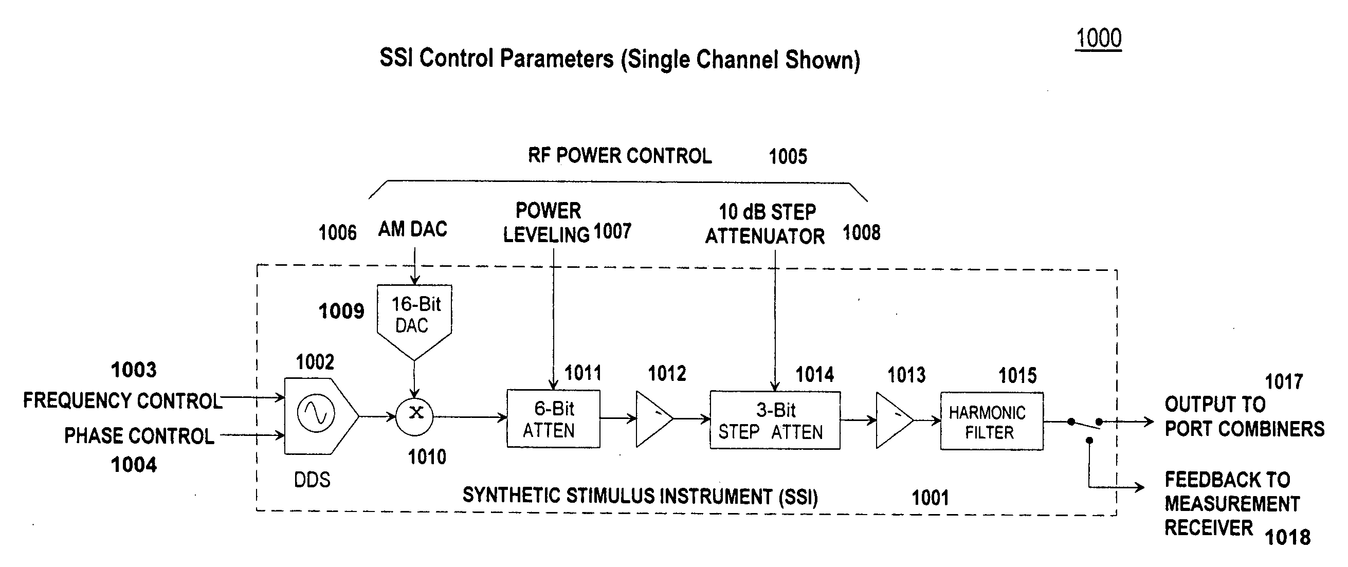
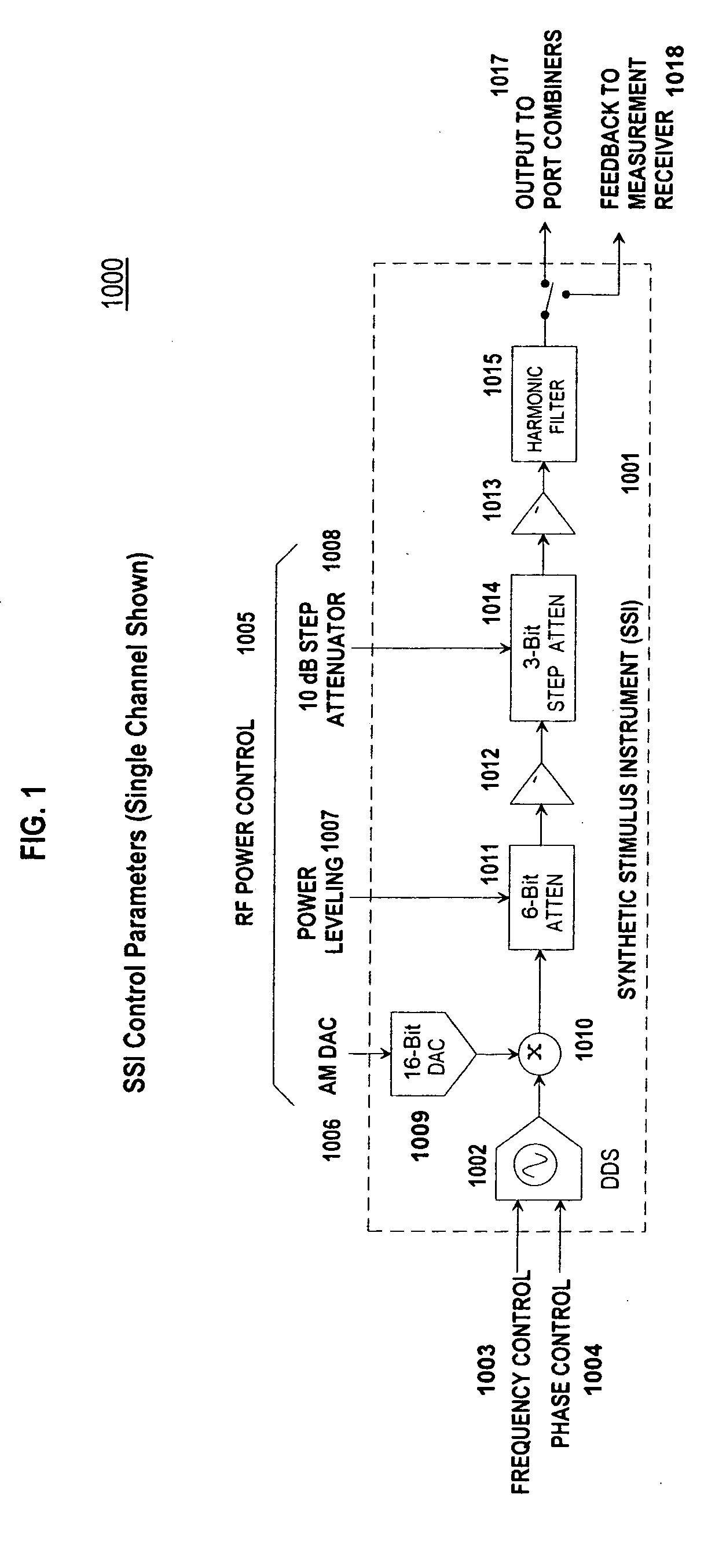
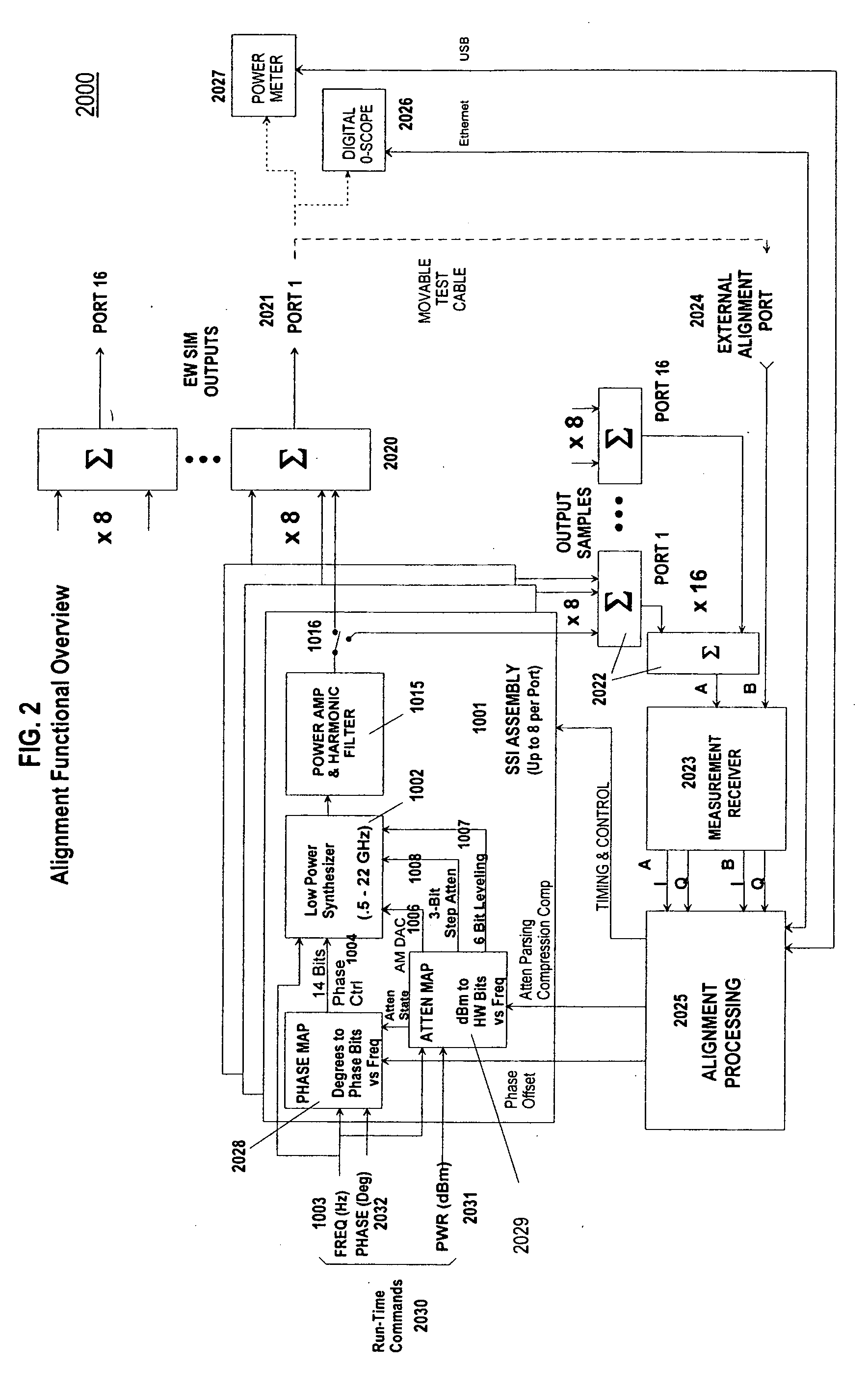
[0007]According to an exemplary embodiment of the present invention, an exemplary feature of this invention may provide a comprehensive, automated method for aligning amplitude, phase, and time, for every signal source in an EW simulator. The EW simulator may contain, in an exemplary embodiment, an arbitrary number of signal sources (such as, e.g., but not limited to, typically, 96 or more). A feature of an exemplary embodiment of the EW simulator may perform alignment on a time-line that permits every signal source in the system to be fully aligned, at every possible frequency and at every possible attenuation state, in, e.g., but not limited to, less than, or about equal to, 15 minutes. In addition, the method disclosed herein, according to an exemplary embodiment, may provide a continuous, on-going alignment of the system so that signal characteristics may be constantly realigned (e.g., but not limited to, approximately once per second) to eliminate effects of thermal drift.
[0009]According to one exemplary embodiment, the method may further include providing power leveling to improve accuracy.

Problems solved by technology

Even so, the conventional alignment process is a time-consuming, tedious operation, and it is not at all uncommon to get reports from users that they spend more time aligning, than they do using, these systems.
This need implies that the alignment problem, already time-consuming and tedious to the extent that it is a significant impediment to system operation, must be extended to somehow support alignment of phase across frequency.

Method used


Image

  • Method for implementing continuous radio frequency (RF) alignment in advanced electronic warfare (EW) signal stimulation systems
  • Method for implementing continuous radio frequency (RF) alignment in advanced electronic warfare (EW) signal stimulation systems
  • Method for implementing continuous radio frequency (RF) alignment in advanced electronic warfare (EW) signal stimulation systems

Examples


Embodiment Construction

Overview of an Exemplary Embodiment of the Present Invention

[0038]Exemplary embodiments of the invention are discussed in detail below. In describing exemplary embodiments, specific terminology may be employed for the sake of clarity. However, the invention is not intended to be limited to the specific terminology so selected. While specific exemplary embodiments may be discussed, it should be understood that this is done for illustration purposes only. A person skilled in the relevant art will recognize that other components and configurations can be used without parting from the spirit and scope of the invention.

[0039]Exemplary embodiments of the present invention may include apparatuses for performing the operations herein. An apparatus may be specially constructed for the desired purposes, or it may comprise a general purpose device selectively activated or reconfigured by a program stored in the device.

[0040]Exemplary embodiments of the invention may be implemented in one or a ...


PUM


Abstract

A method of providing an integrated approach to automated system alignment is set forth, which may include in an exemplary embodiment: providing amplifier compression alignment, (which may include characterizing and / or compensating for a parasitic effect); providing continuous internal alignment of phase and amplitude of a synthetic stimulus instrument (SSI) output signal; providing external measurement port alignment; and providing transfer alignment of internal measurement paths. According to another exemplary embodiment, a receiver apparatus may include: a dual-channel coherent measurement receiver which may include at least one internal channel operative to measure time-division-multiplexed (TDM) feedback signals from each signal source of a synthetic stimulus instrument (SSI); and at least one external channel operative to make direct measurement at an external alignment port output.

Description

BACKGROUND OF THE INVENTION[0001]1. Field of the Invention[0002]The present invention relates generally to simulation systems, more particularly to electronic warfare (EW) simulation systems, and even more specifically, to the issue of aligning laboratory EW simulation systems.[0003]2. Related Art[0004]Electronic warfare (EW) simulation systems in a laboratory must be aligned. These simulation systems may typically include multiple signal sources (such as, e.g., but not limited to, modulated microwave synthesizers), in which each of these signal sources may be capable of producing time-interleaved microwave pulses of different frequencies and modulation characteristics, so as to emulate the signal characteristics of a multiplicity of radar emitters. The simulation systems may be arranged to output similar RF signals on multiple channels, with controlled differences in specific parameters between channels.[0005]Such systems must be aligned in order to ensure that the signals these sy...

Claims


Application Information

Patent Timeline
IPC IPC(8): G01S7/40
CPCG01R35/005G01R31/2841G01S7/38G01S7/4052
Inventor JAKLITSCH, JAMES J.MARKEY, JAYMCGRATH, THOMAS P.
Owner AIRPORTS AUTHORITY OF INDIA
Learn More