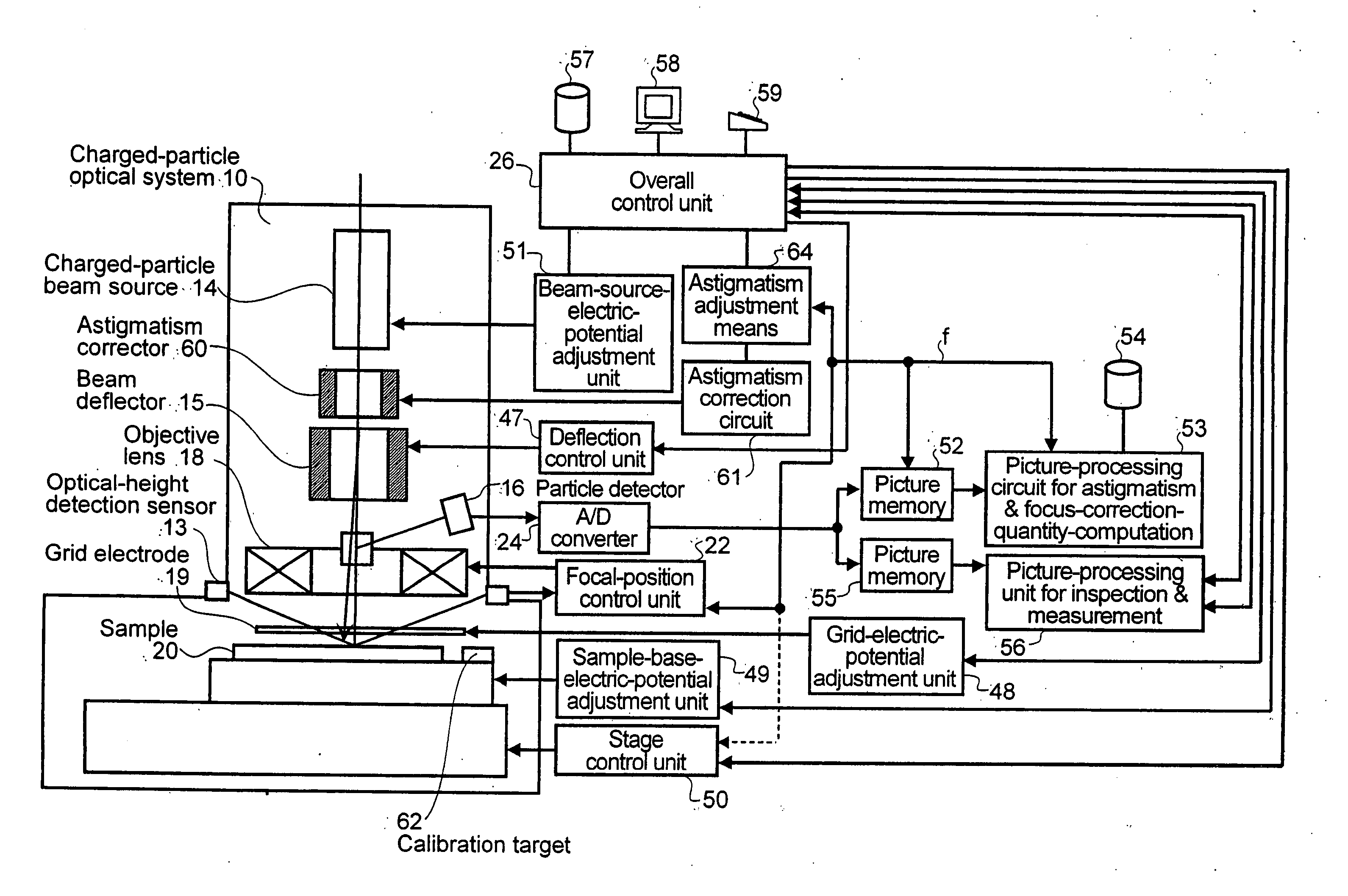
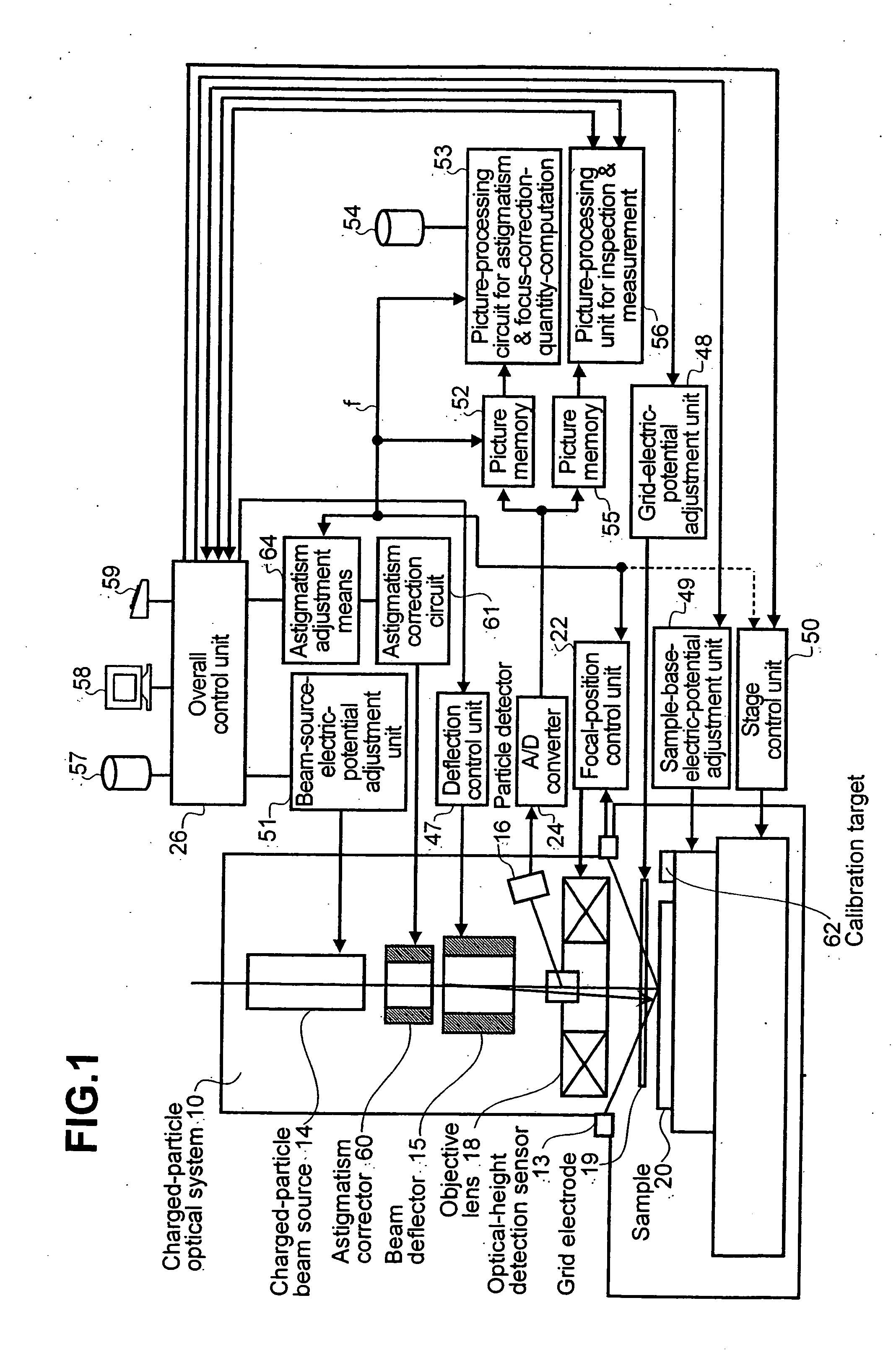
Charged-particle beam apparatus and method for automatically correcting astigmatism and for height detection
a beam apparatus and beam beam technology, applied in the direction of material analysis using wave/particle radiation, instruments, nuclear engineering, etc., can solve the problems of high processing time, sample damage, and a lot of time to measure an optimum control current before inspection
- Summary
- Abstract
- Description
- Claims
- Application Information
AI Technical Summary
Problems solved by technology
Method used
Image
Examples
first embodiment
[0177] As a first embodiment, a particle image is detected and observed by the particle detector 16. The particle image is detected by radiating a charged-particle beam to a sample (target) 62 in a scanning operation. The target 62 is used specially for automatic correction of astigmatism. The sample 62 has a striped pattern with a stripe direction varying from area, to area as shown in FIG. 7(a). The directional sharpness dθ is found by measuring the amplitude of a particle image in each area. The amplitude can be found by directly measuring an amplitude {=a maximum value of s (x, y)−a minimum value of s (x, y)} in each area or by measuring a variance of a concentration quantity (gradation quantity) of a particle image in each area. The variation V is expressed by the following equation:
V=Σxy(s(x,y)−s mean)2 / N.
As an alternative, the amplitude can also be found by computing a sum of absolute values Σxy|t(x, y)| or a sum of squares Σxy(t(x, y))2, where notation t (x, y) denotes a d...
second embodiment
[0178] A second embodiment is provided for a pattern created on the sample 20 or the target 62, as shown in FIG. 7(b). In this case, the directional sharpness dθ is found by carrying out a directional-differentiation process on a particle image detected by the particle detector 16. The directional-differentiation process is carried out by convolution of a mask, similar to the one shown in the figure, on the image. Then, a sum of squares of values at all points on the image of a differentiation is computed so as to be used as the directional sharpness dθ. The differentiation mask shown in the figure is a typical mask. Any mask other than the typical mask can be used as long as the other mask satisfies a condition for the differentiation. The condition requires that two pieces of data at any two positions symmetrical with each other with respect to a certain axis shall have signs opposite to each other and equal absolute values. For suppression of noise and improvement of direction se...
PUM
 Abstract
Description
Claims
Application Information
 - R&D
- Intellectual Property
- Life Sciences
- Materials
- Tech Scout
- Unparalleled Data Quality
- Higher Quality Content
- 60% Fewer Hallucinations
Browse by: Latest US Patents, China's latest patents, Technical Efficacy Thesaurus, Application Domain, Technology Topic, Popular Technical Reports.
© 2025 PatSnap. All rights reserved.Legal|Privacy policy|Modern Slavery Act Transparency Statement|Sitemap|About US| Contact US: help@patsnap.com


